
Sealing device for a dual clutch transmission of a motor vehicle

a dual-clutch transmission and sealing device technology, which is applied in the direction of fluid couplings, gearings, road transportation, etc., can solve the problems of affecting the sealing tightness of the configuration, the radial shaft sealing rings are acted on by rotational speed, and the drain used for ventilation and aeration, leak detection, etc., to achieve reliable and sturdy sealing, high functional integration of the mounting component, and effective use of the structural space in the transmission

Inactive Publication Date: 2013-03-26
ZF FRIEDRICHSHAFEN AG +1
View PDF18 Cites 0 Cited by
  • Summary
  • Abstract
  • Description
  • Claims
  • Application Information

AI Technical Summary

Benefits of technology

The invention is about a new way to prevent leakage and damage from centrifugal forces in a double clutch transmission with separate oil chambers for the double clutch and the transmission. The solution involves using two sealing elements that are fastened to the housing and integrated into the transmission design, creating a secure and sturdy seal in the housing. The sealing elements are configured as double sealing rings, which provide an oil-free chamber for ventilation and / or aeration, and can detect leaks of transmission oil or clutch oil. The mounting component also has additional functions, such as accommodating an intermediate bearing for a reverse gear, which helps to load distribute the transmission more effectively. The new design allows for a more compact double clutch transmission and reduces the structural space required.

Problems solved by technology

However, double clutch transmissions have the problem that the oil chambers must also be sealed off from one another directly in the area in which the radially interior drive shaft emerges from the radially exterior drive shaft inside the transmission chamber, because the two oil chambers are connected to one another via an annular gap between the shafts.
The disadvantage of this configuration is that the radial shaft sealing rings are acted upon by rotational speed as the exterior hollow shaft rotates.
The resulting centrifugal forces can cause the sealing lips to separate from the central drive shaft, thereby impairing the seal tightness of the configuration.
In addition, the drain used for ventilation and aeration, as well as for leak detection, is a relatively complicated structurally.

Method used


Image

  • Sealing device for a dual clutch transmission of a motor vehicle
  • Sealing device for a dual clutch transmission of a motor vehicle
  • Sealing device for a dual clutch transmission of a motor vehicle

Examples


Embodiment Construction

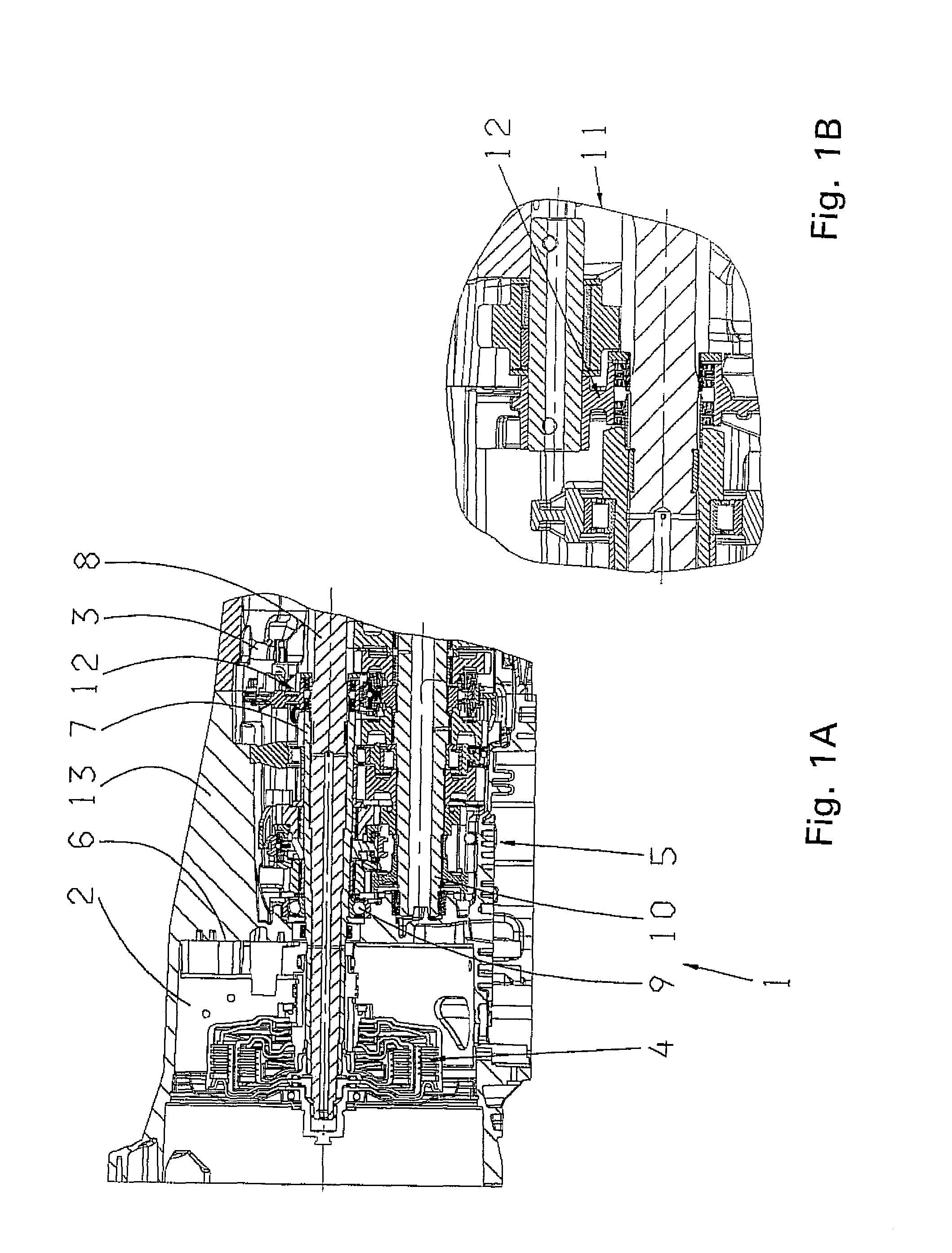
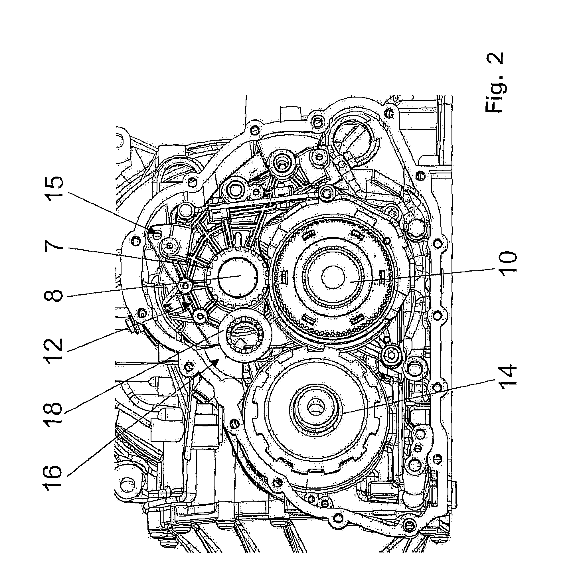
[0032]According to the above, FIGS. 1A and 1B show a double clutch transmission 1 of a motor vehicle with separate oil chambers 2, 3. Oil chamber 2 is configured as a clutch chamber for accommodating a wet multi-plate, double clutch 4. Oil chamber 3 is configured as a transmission chamber, which accommodates a double clutch transmission set 5 in the sense of two partial transmissions. Oil chambers 2 and 3 are enclosed inside a shared transmission housing 13. The manner in which a double clutch transmission functions is known per se, therefore, in what follows, only the sealing device of the invention will be addressed in detail.

[0033]The oil chambers 2, 3 are separated by a dividing wall 6, through which two drive shafts run. The first drive shaft is configured as a hollow shaft 7, in which the second drive shaft is inserted co-axially as a central shaft 8. Each of the two shafts 7 and 8 is rotatably mounted and is connected to a single clutch of the double clutch 4 in the clutch ch...


PUM


Abstract

A device for sealing a double clutch transmission of a motor vehicle, with a transmission housing, in which are arranged a clutch chamber with clutch oil and a double clutch, a transmission chamber with transmission oil and a double clutch transmission wheel set and two co-axial drive shafts disposed, one inside the other. One drive shaft is an interior central shaft which extends inside the transmission chamber from the end of the second hollow drive shaft. The two drive shafts each have a sealing element to seal the clutch chamber from the transmission chamber. A mounting component is situated inside and fixed to the transmission housing to support two adjacent sealing elements. A first sealing element forms a seal radially on the hollow drive shaft and a second sealing element forms a seal radially on the central drive shaft to provide a reliable seal and offer a simple ventilation and leakage detection.

Description

[0001]This application is a national stage completion of PCT / EP2006 / 011436 filed Nov. 29, 2006, which claims priority from German Application Serial No. 10 2005 057 294.4 filed Dec. 1, 2005.FIELD OF THE INVENTION[0002]The invention relates to a device for sealing a double clutch transmission of a motor vehicle.BACKGROUND OF THE INVENTION[0003]Double clutch transmissions for motor vehicles are known in the art. Their principal advantage over conventional stepped manual transmissions is that the shifting processes of a gear change take place almost without interruption in propulsive force. In this manner, frequent changes in acceleration and load during gear shifting are avoided, resulting in more comfortable handling and enabling a sportier driving mode. In a popular construction, described in DE 101 34 118 A1, the double clutch transmission is equipped with two drive shafts (transmission input shafts), which are arranged co-axially in relation to one another, each with a friction cl...

Claims


Application Information

Patent Timeline
IPC IPC(8): F16D21/06F16D25/0638F16H57/04F16D13/46
CPCF16H57/0401F16H3/006Y10T74/19228Y02T10/76Y10T74/19991F16H57/0454
Inventor KRAXNER, DIETERHOBEL, PETERRETTENMAIER, MARKUSPATZNER, JENS
Owner ZF FRIEDRICHSHAFEN AG
Learn More