
Mounting device

a technology of mounting device and screw, which is applied in the direction of machine supports, snap fasteners, buckles, etc., can solve the problems of high production cost and complexity, risk of injury, and the inability to use plastic hook-and-loop closures, so as to improve the corrosion resistance or sliding friction

Active Publication Date: 2014-12-02
REINZ DICHTUNGS +1
View PDF16 Cites 8 Cited by
  • Summary
  • Abstract
  • Description
  • Claims
  • Application Information

AI Technical Summary

Benefits of technology

The invention is a mounting device for a hook-and-loop closure that can be used with different variations of counterparts. It can hold things securely, and it is easy to use and produce. This invention can be used for almost any purpose and in almost any orientation. Its goal is to provide a versatile and efficient mounting solution for hook-and-loop closures.

Problems solved by technology

For a large range of applications, these plastic hook-and-loop closures can however not be used, as they do not provide for the necessary durability and temperature stability or as they show no electrical conductivity.
The counterparts made from metal wire however have the drawback that on the one hand their production is expensive and elaborate and on the other hand that the metallic scrim tends to fray and the metallic loops beak, which provides a risk for injury and reduces the durability.
Perforated metal sheets have the disadvantage that the mounting protrusions can only be fixed in a distinct orientation in the counterpart.
This considerably restricts the applicability of these counterparts.

Method used


Image

  • Mounting device
  • Mounting device
  • Mounting device

Examples


Embodiment Construction

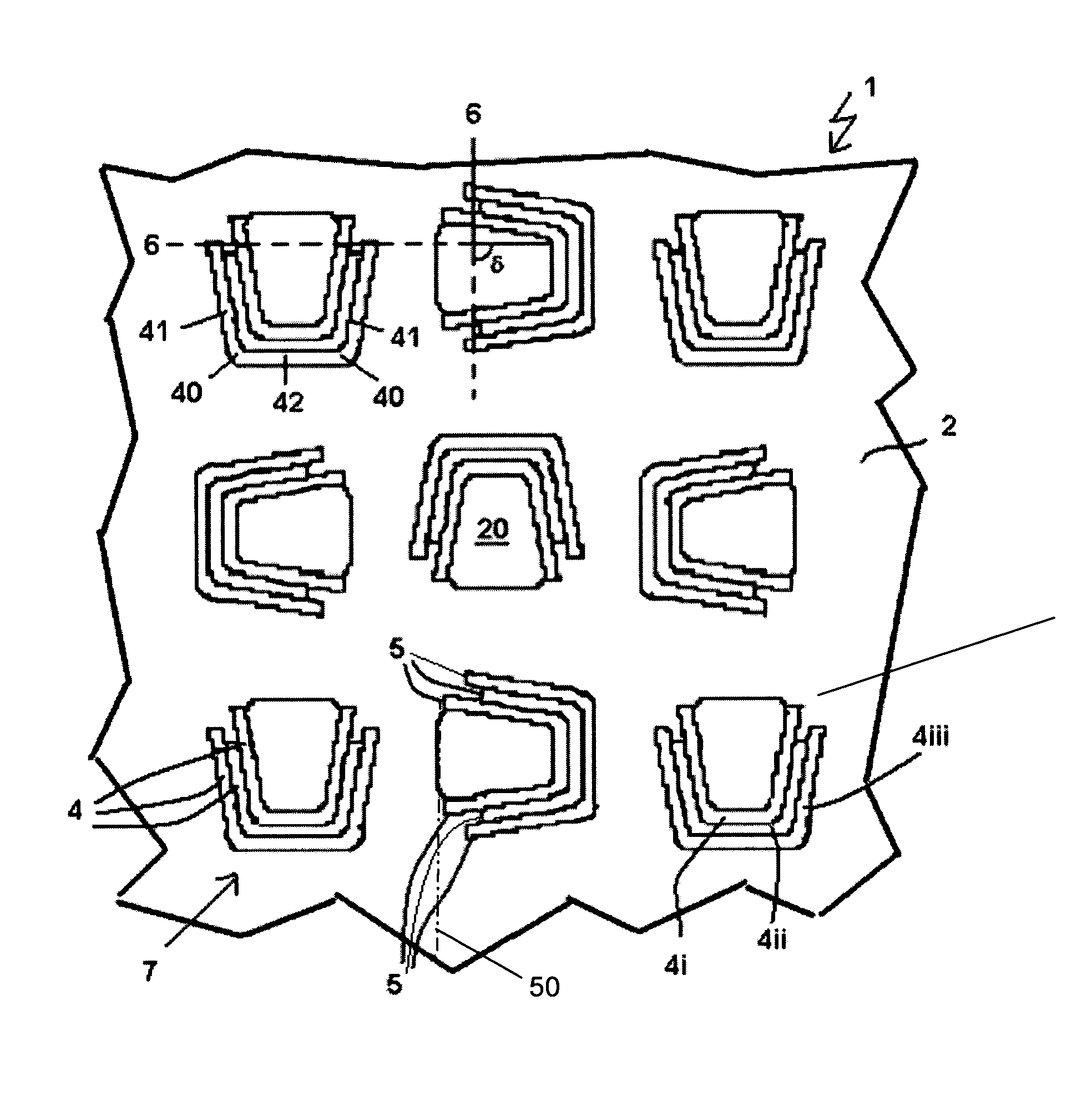
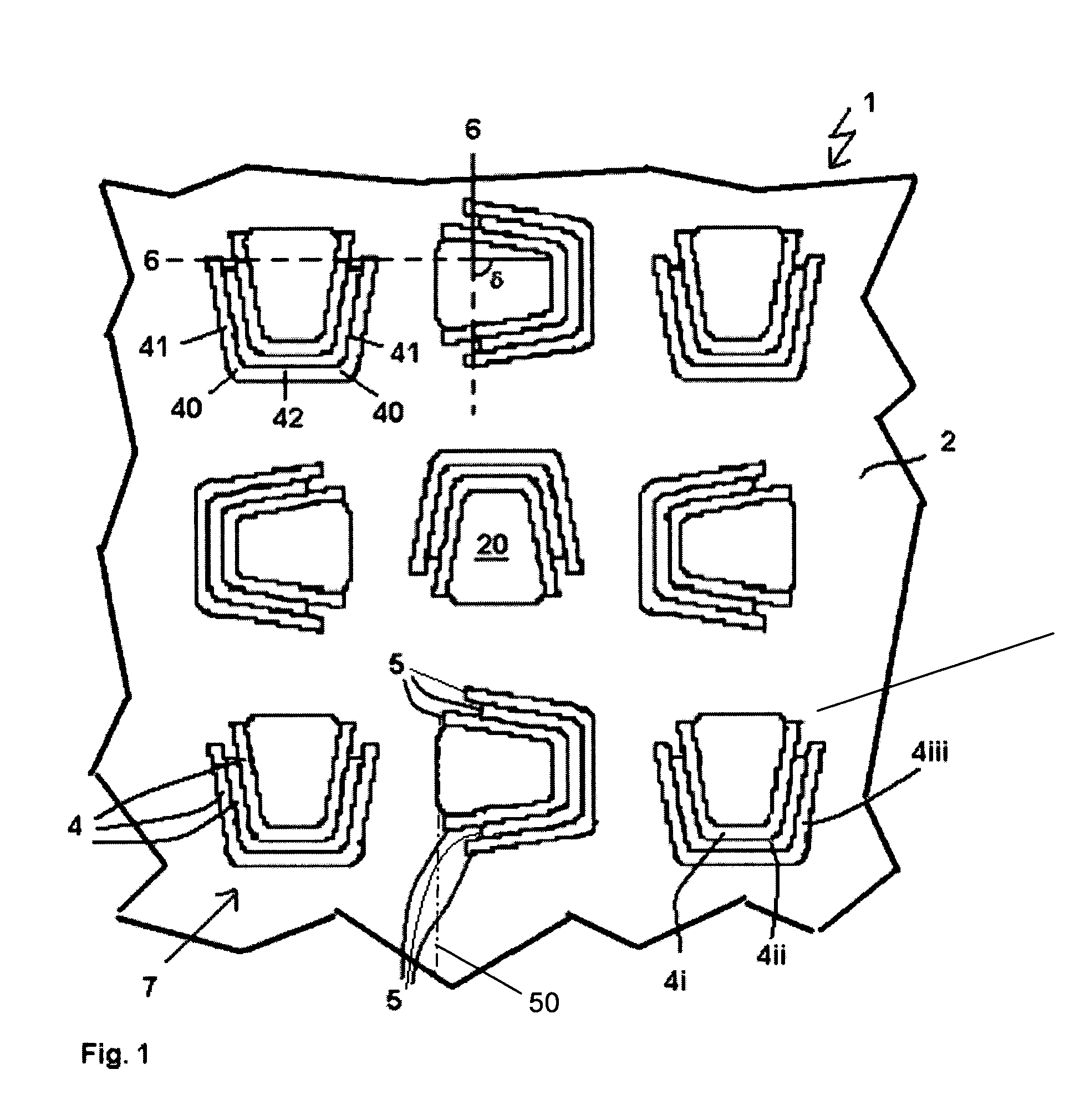
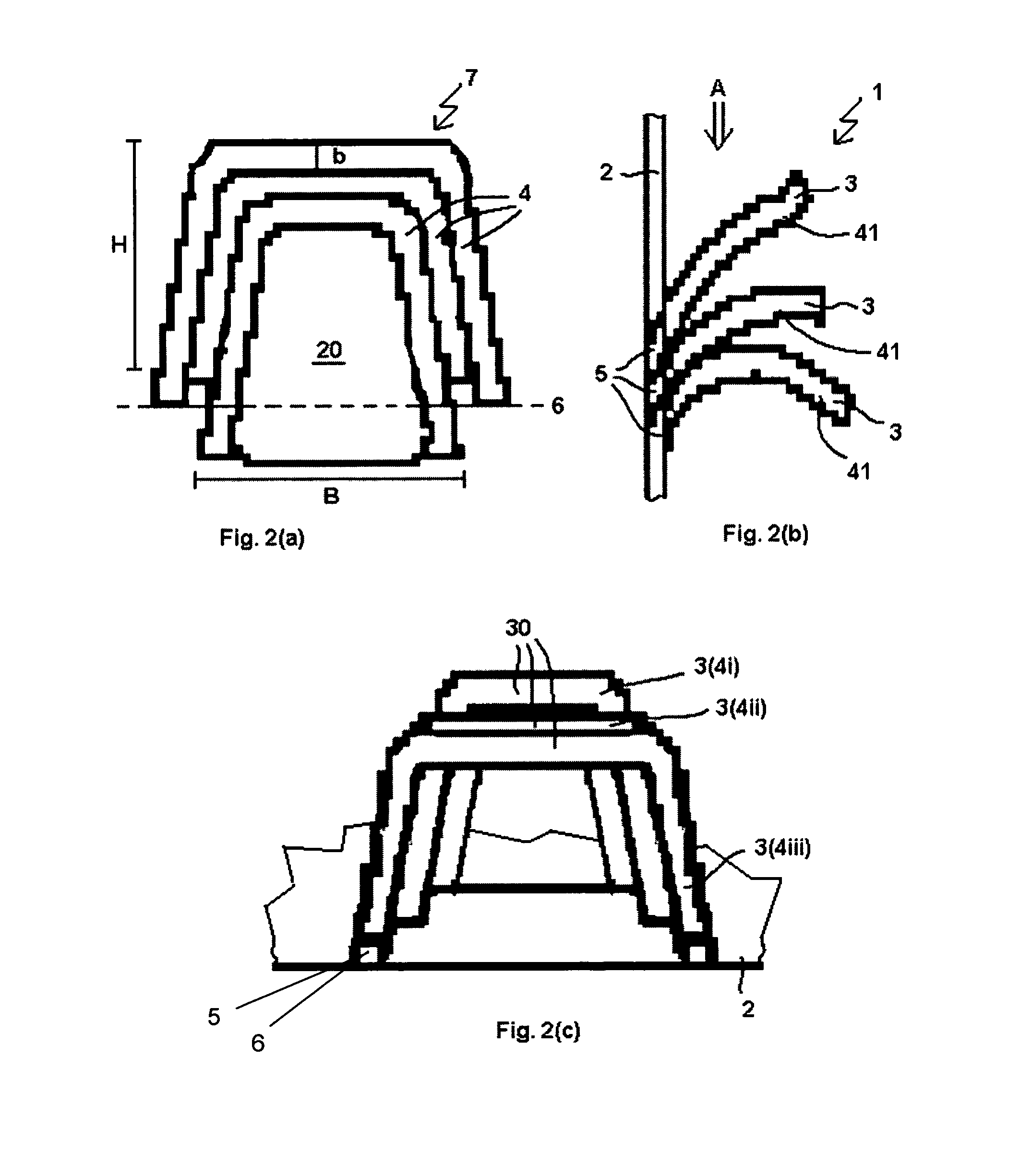
[0044]FIG. 1 shows a first example of a mounting device 1 according to the invention in a top view to the metallic base plate 2, which consists for example of spring steel. In this base plate 2, a total of nine groups 7 are incised which each comprise three eyelet blanks 4. As already mentioned earlier, the term blank does not comprise any restrictions with respect to order of production for the eyelets but only prescribes the geometry of the part which is bent out of the plane either after or during incising. The eyelet blanks 4 are formed as arc-shaped and in general have a U-shape. They show two angles 40, which are each followed by a flank 41 and between which a flattened crest plateau 42 extends. All eyelet blanks 4 are detached from the base plate 2 along their lateral edges of the flanks 41, the angles 40 and the crest plateau 42, they are only connected to the base plate in the area of the connection sections 5 next to the foot points of the flanks 41. Within each group 7, t...


PUM

PropertyMeasurementUnit
heightaaaaaaaaaa
heightaaaaaaaaaa
widthaaaaaaaaaa

Abstract

A mounting device with one metallic base plate, from which a plurality of mounting eyelets protrude. The mounting device is obtainable by incising a plurality of arc-shaped eyelet blanks while leaving two connection sections per eyelet blank into the surface of the base plate and production of the mounting eyelets by bending the eyelet blanks out of the base plate around a bending edge in the area of the connection sections. At least part of the eyelet blanks are arranged as groups of eyelet blanks with the latter being nested to each other. Preferably, the groups of eyelet blanks are arranged rotated relative to each other.

Description

BACKGROUND OF THE INVENTION[0001]The invention relates to a mounting device with a metallic base plate, above which a plurality of mounting eyelets protrude, and a method for the production of such a mounting device.[0002]In many industrial and other areas (e.g. building, automobile production, household etc.) it is regularly necessary to mount metallic parts or components or to connect them with other parts. There it is often desirable to produce the mounting devices and the closure in a simple and rapid manner, without the need of special tools, such as welding or screwing tools for the mounting. In the field of plastic parts, such a mounting is achieved by use of hook-and-loop closures as mounting devices. For a large range of applications, these plastic hook-and-loop closures can however not be used, as they do not provide for the necessary durability and temperature stability or as they show no electrical conductivity. Therefore, the application has already proposed mounting de...

Claims


Application Information

Patent Timeline
Patent Type & Authority Patents(United States)
IPC IPC(8): F16M13/00B21D31/00F16B5/07
CPCF16B5/07B21J5/12Y10T24/27Y10T24/2775Y10T24/2792B21J5/068
Inventor BRAUN, KLAUSCARLE, GABIHOEHE, KURTRUESS, BERNDLASKE, MATTHIAS
Owner REINZ DICHTUNGS
Learn More