
Construction of planar rechargeable oxide-ion battery cells and stacks using stainless steel housing structures

a rechargeable oxide-ion battery and stainless steel technology, applied in the direction of batteries, cell components, jackets/case materials, etc., can solve the problems of affecting the efficiency of battery cells, and being almost completely displaced from the market, so as to reduce cell ohmic loss

Inactive Publication Date: 2014-11-25
SIEMENS ENERGY GLOBAL GMBH & CO KG
View PDF11 Cites 2 Cited by
  • Summary
  • Abstract
  • Description
  • Claims
  • Application Information

AI Technical Summary

Benefits of technology

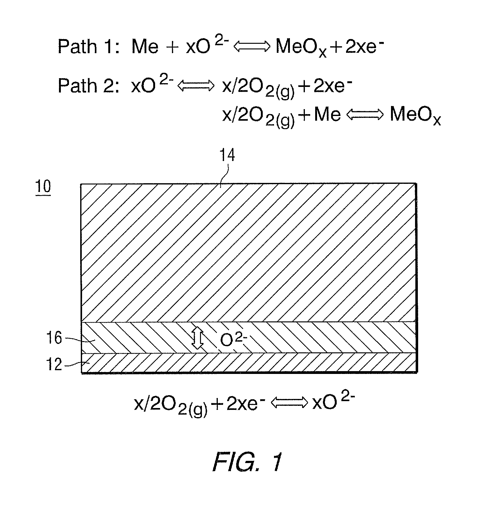
[0012]The above needs for producing a ROB cell and stack are supplied and object accomplished by utilizing a cell membrane assembly, stainless steel housing structure, seal(s), and electrical collector(s). The construction of the planar ROB cell and stack, has an oxidation resistant metal housing, such as nickel-based alloys, chromium-based alloys or iron-based alloys, preferably stainless steel. The planar design, compared with tubular designs, reduces cell Ohmic loss. Both electrolyte supported and skeleton supported cells can be accommodated in the planar design. The ROB cell of this invention uses brazing and welding seals to separate active metal components from air, and also has compliant cell-to-cell current collectors.

Problems solved by technology

The present electrochemical energy storage systems are simply too costly to penetrate major new markets.
NiMH batteries were the initial workhorse for electronic devices such as computers and cell phones, but they have almost been completely displaced from that market by lithium-ion batteries because of the latter's higher energy storage capacity.
Today, NiMH technology is the principal battery used in hybrid electric vehicles, but it is likely to be displaced by the higher power energy and now lower cost lithium batteries, if the latter's safety and lifetime can be improved.
Otherwise, oxygen in air will directly consume the metal without involving charge transfer between electrodes, which will lead to self discharge.

Method used


Image

  • Construction of planar rechargeable oxide-ion battery cells and stacks using stainless steel housing structures
  • Construction of planar rechargeable oxide-ion battery cells and stacks using stainless steel housing structures
  • Construction of planar rechargeable oxide-ion battery cells and stacks using stainless steel housing structures

Examples


Embodiment Construction

[0030]The requirements of a ROB cell include:[0031]a) an air electrode for reversible conversion of oxygen into an oxide ion (O2−) that carries / has two electrical charges;[0032]b) an oxide-ion conductive electrolyte for transporting electrical charge in the form of O2−;[0033]c) a metal electrode where electrical charge associated with the oxide-ion is stored or released by an active metal component(s), and for accommodating the volume change associated with a metal redox reaction;[0034]d) a reliable seal separating direct contact between air and active metal; and[0035]e) cost effectiveness.

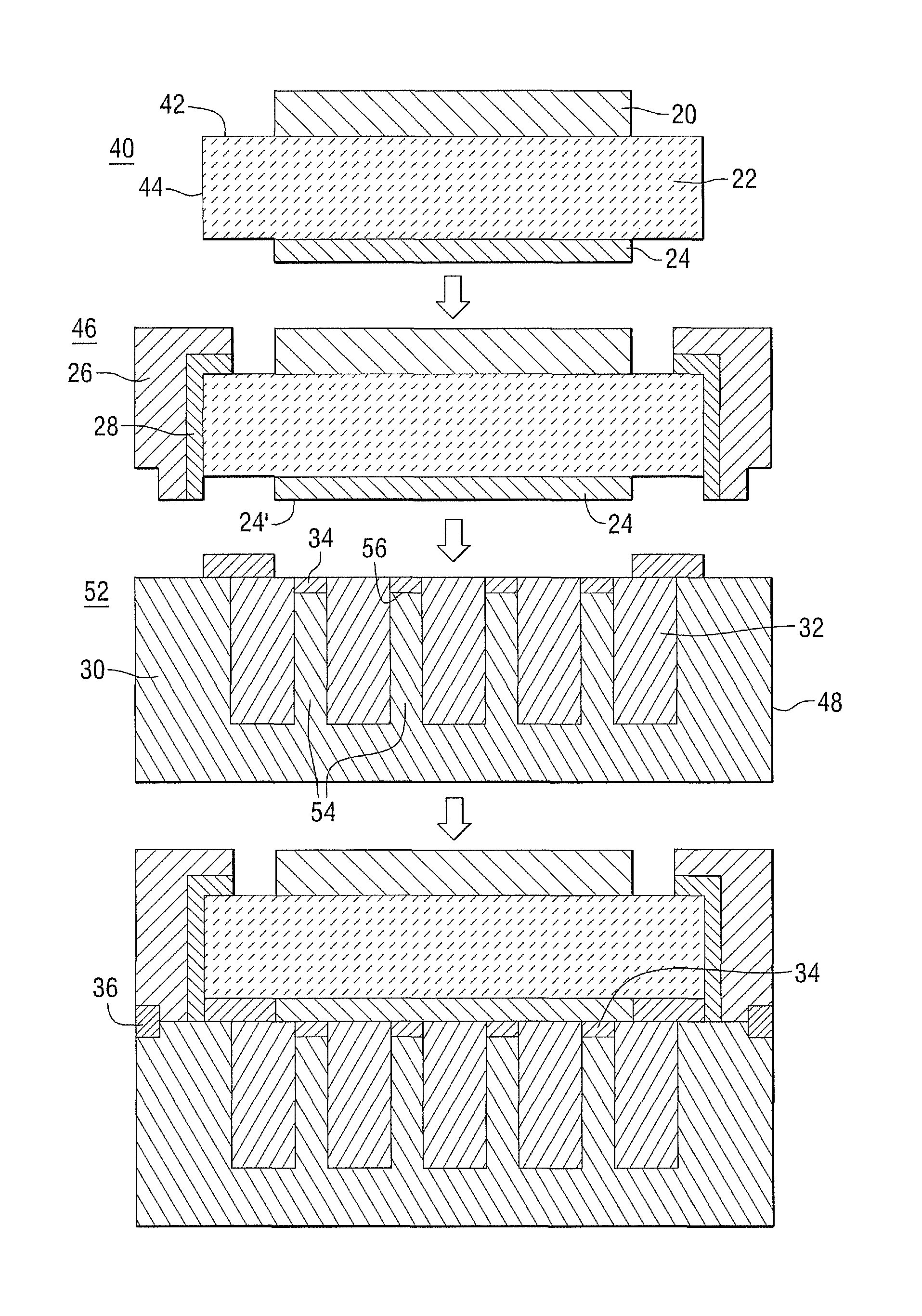
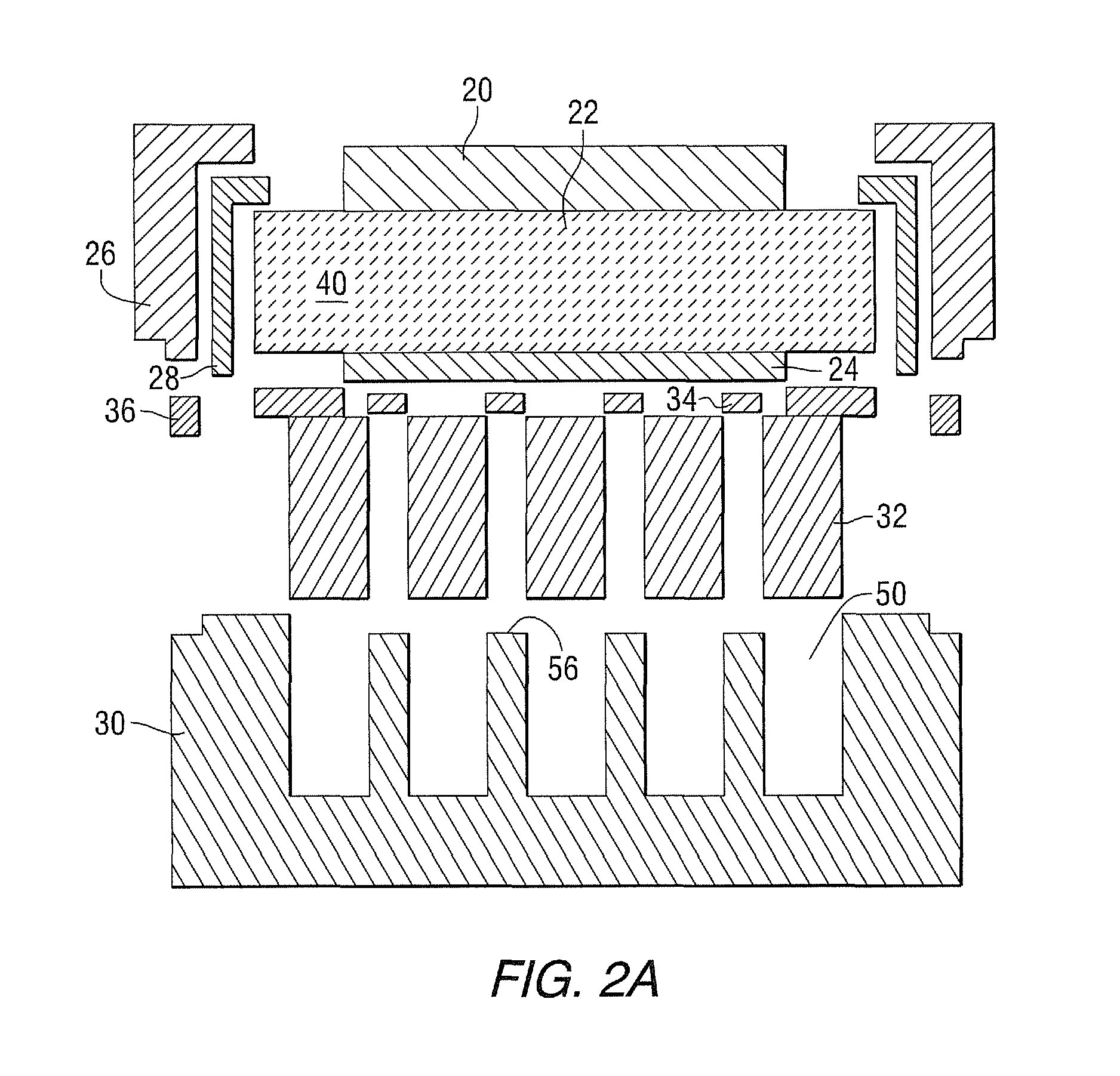
[0036]Referring now to FIGS. 2A and 2B, which show a schematic illustration of joining components (2A), and which show a finished planar ROB cell (2B). The top air electrode is shown as 20, while 22 shows a sandwiched ceramic middle electrolyte, and 24 shows the bottom metal electrode. Components 20, 22 and 24 together form a membrane assembly, generally shown as 40, best shown in FIG. 3. In FIGS....


PUM

PropertyMeasurementUnit
thicknessaaaaaaaaaa
temperatureaaaaaaaaaa

Abstract

Processing steps for constructing a rechargeable oxide-ion battery (ROB) cell using a cell membrane assembly 40 and a hollow metal housing structure 30 wherein assembly steps include: a) forming a membrane assembly 40 of air electrode 20, metal electrode 24 and electrolyte 22 therebetween; b) sealing the membrane assembly 40 to a surrounding frame 26; c) filling the hollow metal housing structure 30 with active material 32; d) forming electrical contact between the framed membrane assembly and the filled housing structure; and e) joining the framed membrane assembly and the active housing structure to form a ROB cell.

Description

BACKGROUND OF THE INVENTION[0001]1. Field of the Invention[0002]This present invention relates to engineering methods for constructing rechargeable oxide-ion battery (ROB) cells and stacks. More specifically, the invention details the processing steps using a cell membrane assembly and a stainless steel housing structure.[0003]2. Description of Related Art[0004]Electrical energy storage is crucial for the effective proliferation of an electrical economy and for the implementation of many renewable energy technologies. During the past two decades, the demand for the storage of electrical energy has increased significantly in the areas of portable, transportation, load-leveling and central backup applications. The present electrochemical energy storage systems are simply too costly to penetrate major new markets. Higher performance is required, and environmentally acceptable materials are preferred. Transformational changes in electrical energy storage science and technology are in gr...

Claims


Application Information

Patent Timeline
Patent Type & Authority Patents(United States)
IPC IPC(8): H01M12/08H01M2/20H01M4/36H01M4/76H01M4/90H01M6/00H01M4/38H01M2/02H01M4/48H01M50/119H01M50/503H01M50/522
CPCH01M4/9033H01M2220/10H01M4/48H01M4/38H01M2/0285H01M2/208H01M2300/0074H01M2/027H01M2/0255Y02E60/50H01M4/362H01M4/76H01M12/08Y10T29/49108Y02E60/10H01M50/1385H01M50/545H01M50/522H01M50/503H01M50/119
Inventor LU, CHUNLITZINGER, KEVIN P.
Owner SIEMENS ENERGY GLOBAL GMBH & CO KG
Learn More