Use devices for mechanically secured block assembly systems

Active Publication Date: 2014-11-25
HARRIS J KEVIN +2
View PDF75 Cites 3 Cited by
  • Summary
  • Abstract
  • Description
  • Claims
  • Application Information

AI Technical Summary

Benefits of technology

The invention is a new system for building structures using mechanically secured blocks. The system includes masonry blocks with cavities and an anchor bar that can be inserted into the masonry block. A fastener is used to assemble the masonry block in various ways, such as creating multiple width walls, grade beams, and horizontal decks. The system also includes a footer block and plate, which can further enhance the strength and durability of the structure. The invention improves on existing methods and allows for more efficient and cost-effective building projects.

Problems solved by technology

Historically, no known devices have attempted to address the problem as stated.
The building industry has made little progress for a unitized, post tension system so improvements to the recent unitized post tension systems have not yet been attractive to promotion of the technology.
Even so, blocks have required very special and often complex configurations to even handle rods and plates and then they have taught only limit rods in special blocks.
This teaches precast walls and pass through cable which are specially made, require water, and are not readily re-useable like the new use devices for mechanically secured block assembly systems.
The beams and blocks are special configuration, not readily available and with limited uses.
These are complex and do not anticipate the new use devices for mechanically secured block assembly systems.
However, none of them are found to show a structural unitized post tensioning system as described for the new use devices for mechanically secured block assembly systems in the materials below.
It fails to address the new use devices for mechanically secured block assembly systems and in fact lacks the embodiment for the deck or grade beams.
It also fails to garner the benefits of the multi-wall configuration.
None of the prior art found with a rigorous search teaches all the features and capabilities of the new use devices for mechanically secured block assembly systems.

Method used


Image

  • Use devices for mechanically secured block assembly systems
  • Use devices for mechanically secured block assembly systems
  • Use devices for mechanically secured block assembly systems

Examples


Embodiment Construction

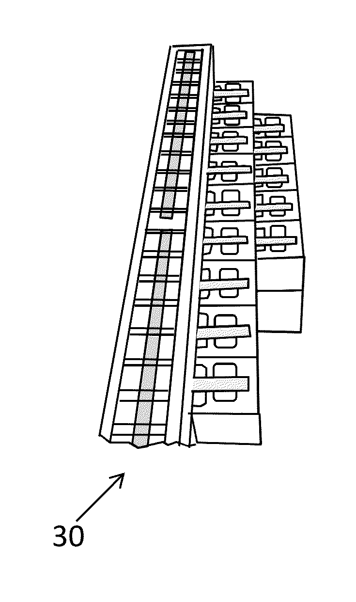
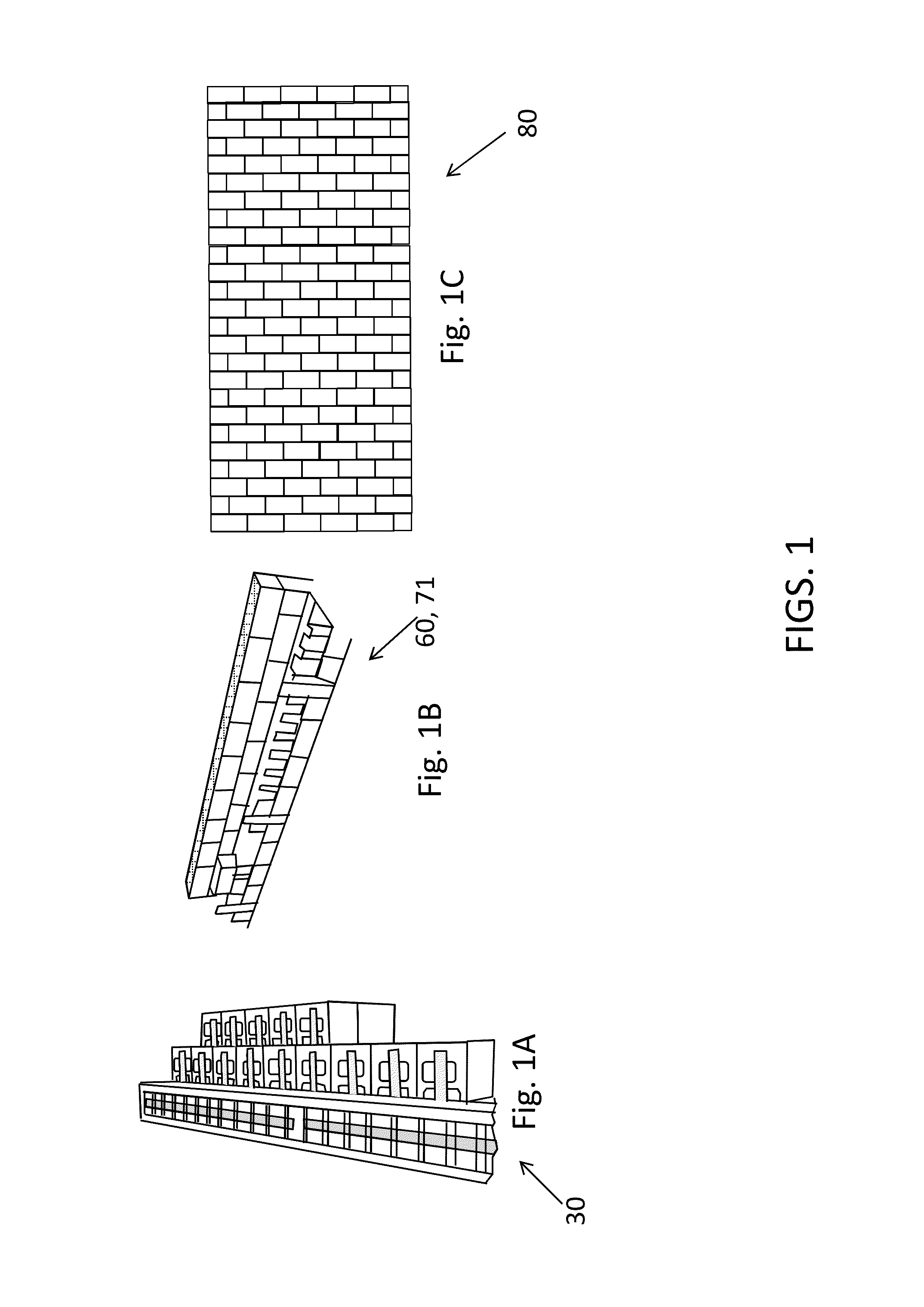
[0042]The present development are new use devices for Mechanically Secured Block (MSB) Assembly Systems. Embodiments of the present invention relate to generally to systems and methods for concrete masonry structures, and more particularly to unitized post tension systems and methods for concrete masonry structures. The present invention relates generally to all types of general construction where a common mortar and hollow block or brick combination is utilized and relates to other construction means, such as reinforced concrete, for structures as well. The embodiments of the New Use devices for Mechanically Secured Block Assembly Systems are shown in the accompanying sketches and described below.

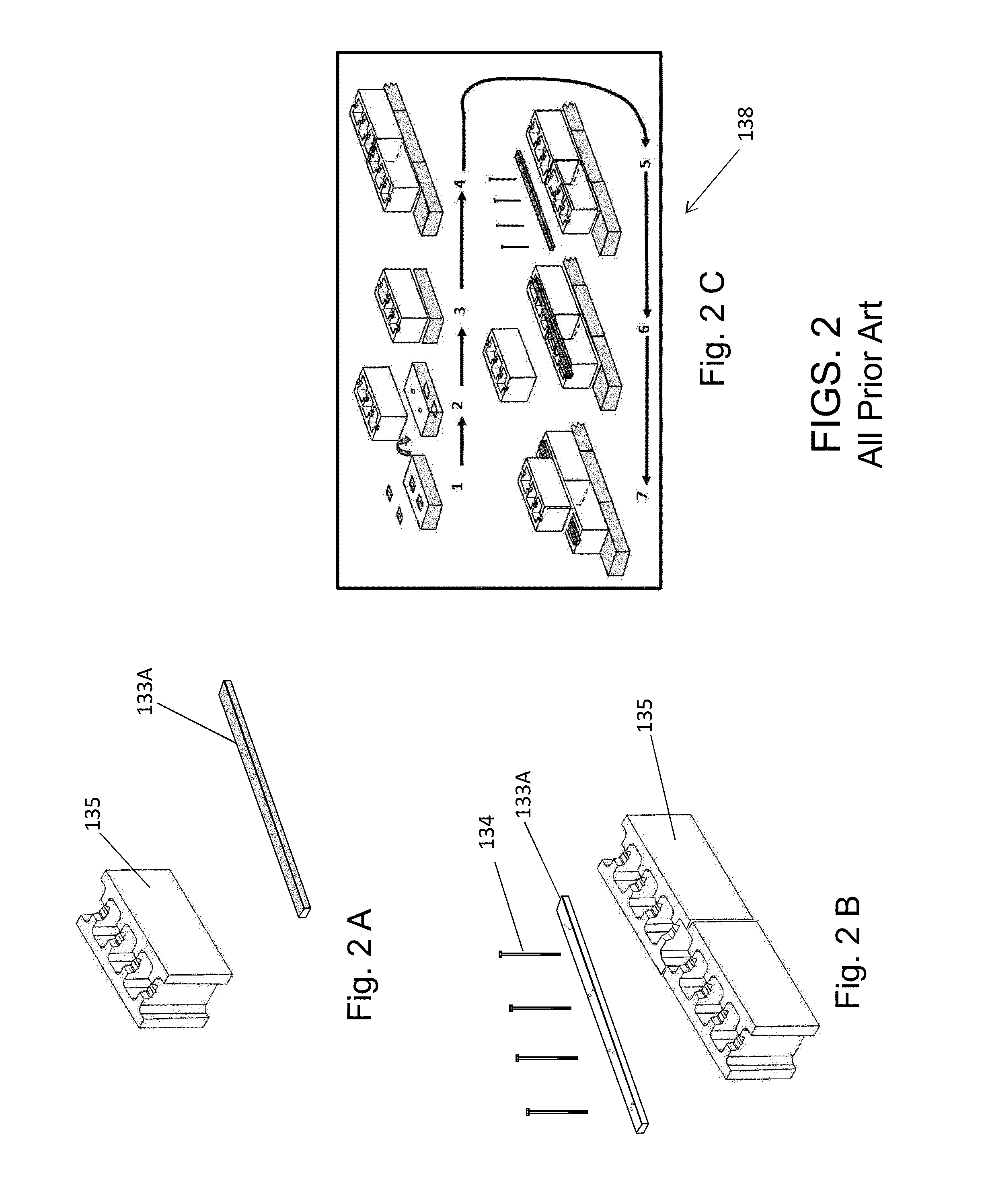
[0043]There is shown in FIGS. 1-16 a complete description and operative embodiment of the new use devices for mechanically secured block assembly systems. In the drawings and illustrations, one notes well that the FIGS. 1-13 demonstrate the general configuration and use of this product / sys...


PUM


Abstract

An improved mechanically secured block building system generally for concrete masonry structures comprising a masonry block unit with a height and width essentially one-half the length of the unit, with multiple cavities through the block and with a recessed channel; an anchor bar with a plurality of threaded and non-threaded apertures in a special configuration to match the cavities in the block unit and able to lay in the recessed channel of the block; and a fastener wherein the mechanical secured block building system can be assembled in unique ways due to a cube effect of the masonry block to construct multiple width walls, grade beams, and horizontal decks. An alternative embodiment includes the preferred mechanical secured block building system further comprised of (d) a footer block and (e) a footer plate.

Description

CROSS-REFERENCE TO RELATED APPLICATIONS[0001]This application claims the benefit of Provisional Patent Application Ser. No. 61 / 733,536 filed Dec. 5, 2012 by Kevin Harris et al and entitled “New Use devices for Mechanically Secured Block Assembly Systems”.FIELD OF INVENTION[0002]Embodiments of the present invention relates to generally to systems and methods for concrete masonry structures, and more particularly to unitized post tension systems and methods for concrete masonry structures. The present invention relates generally to all types of general construction where a common mortar and hollow block or brick combination is utilized and relates to other construction means, such as reinforced concrete, for structures as well.FEDERALLY SPONSORED RESEARCH[0003]None.SEQUENCE LISTING OR PROGRAM[0004]None.BACKGROUND AND PRIOR ART[0005]Existing unitized post tension systems for concrete masonry structures have until now required special other construction to address larger wall widths ove...

Claims


Application Information

Patent Timeline
IPC IPC(8): E04C5/08E04C1/39E04C5/12
CPCE04C1/39E04C5/08E04C5/125E04B2002/0254E04C3/22E04C2003/023E04B1/043E04B1/5825E04B2/18E04B5/08E04B7/00E04B2001/5887E04B2001/5893E04B2002/0247E04B2002/0297E04C1/00E04C5/06E04C5/162E04B2/16E04B2/26E04B2002/0202
Inventor HARRIS, J KEVINERTL, DANRITCHISON, JOHN D
Owner HARRIS J KEVIN
Why Eureka
Try Eureka