
Piezoelectric actuator having a moveable electrode portion

a technology of moving electrodes and actuators, which is applied in piezoelectric/electrostrictive/magnetostrictive devices, piezoelectric/electrostriction/magnetostriction machines, electrical apparatus, etc., can solve the problems of increasing the number of steps in the manufacturing flow for forming individual components, simplifying the configuration, etc., and achieves simple manufacturing flow, simple configuration, and excellent reliability and piezoelectric characteristics.

Active Publication Date: 2014-11-18
MURATA MFG CO LTD
View PDF33 Cites 3 Cited by
  • Summary
  • Abstract
  • Description
  • Claims
  • Application Information

AI Technical Summary

Benefits of technology

The present invention aims to provide a piezoelectric actuator that is simpler and has a simpler manufacturing flow than existing configurations. This is achieved by integrating multiple components into a single mechanism, reducing the number of steps in the manufacturing process.

Problems solved by technology

Therefore, there are a large number of components that constitute the switching element, which also increases the number of steps in the manufacturing flow for forming those individual components.
Thus, no cover is required for the function of the electrical circuit, which also leads to simplification of the configuration.

Method used


Image

  • Piezoelectric actuator having a moveable electrode portion
  • Piezoelectric actuator having a moveable electrode portion
  • Piezoelectric actuator having a moveable electrode portion

Examples


Embodiment Construction

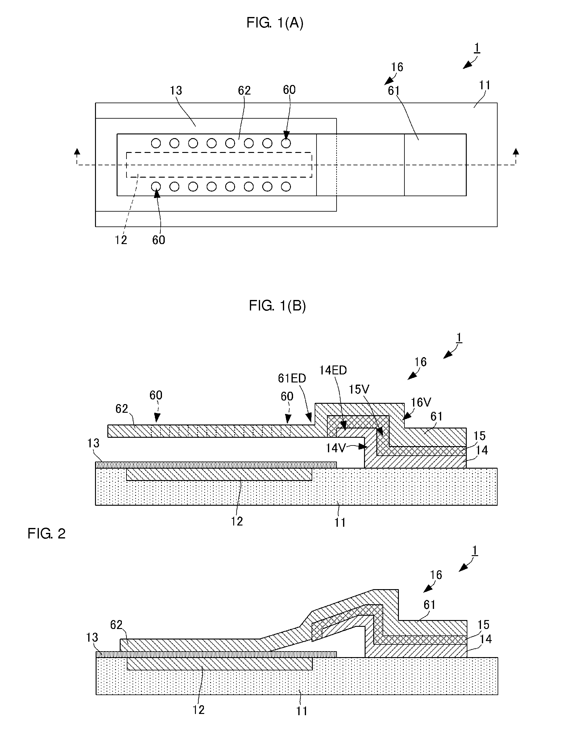
[0049]A piezoelectric actuator according to a first embodiment of the present invention is described with reference to the drawings. FIG. 1(A) is a plan view of a piezoelectric actuator 1 according to this embodiment, and FIG. 1(B) is a side cross-sectional view of the same. FIG. 2 is a side cross-sectional view of the movable portion of the piezoelectric actuator 1 in a bent state.

[0050](Structure of Piezoelectric Actuator)

[0051]As illustrated in FIG. 1(A), the piezoelectric actuator 1 has an insulating base substrate 11 with a predetermined area and a predetermined thickness. The base substrate 1 is formed with a length of 1.5 mm and a width of 0.5 mm in plan view, for example. A recess is formed in a predetermined region on one principal surface (top side in FIG. 1(B)) of the base substrate 11. A fixed electrode 12 is formed inside the recess.

[0052]A dielectric layer 13 is formed in a predetermined region on the surface (one principal surface) of the base substrate 11 where the f...


PUM

PropertyMeasurementUnit
frequenciesaaaaaaaaaa
widthaaaaaaaaaa
lengthaaaaaaaaaa

Abstract

A piezoelectric actuator that includes a fixed electrode in a base substrate, a dielectric layer on the surface of the base substrate, a lower electrode that is at least partially separated from the base substrate, a piezoelectric layer on the surface of the lower electrode, and an upper electrode on the side of the surface of the piezoelectric layer. At least a portion of the upper electrode or the lower electrode serves as a movable electrode, which can be moved by distortion of the piezoelectric layer caused by application of a piezoelectric drive voltage.

Description

CROSS REFERENCE TO RELATED APPLICATIONS[0001]The present application is a continuation of International application No. PCT / JP2011 / 058697, filed Apr. 6, 2011, which claims priority to Japanese Patent Application No. 2010-099778, filed Apr. 23, 2010, the entire contents of each of which are incorporated herein by reference.FIELD OF THE INVENTION[0002]The present invention relates to a piezoelectric actuator that performs electrical control by using a piezoelectric material.BACKGROUND OF THE INVENTION[0003]Currently, various switching elements configured by MEMS elements have been designed. As disclosed in Patent Document 1, for example, some of these switching elements use a piezoelectric actuator.[0004]In the switching element based on a piezoelectric actuator disclosed in Patent Document 1, a cantilever arm is attached to the surface of a base substrate. The arm includes a vertical wall portion serving as a cantilever support portion and having a wall surface orthogonal to the base...

Claims


Application Information

Patent Timeline
Patent Type & Authority Patents(United States)
IPC IPC(8): H01L41/22H01L41/331H01L41/316H01L41/08
CPCH01L41/1873H01L41/331H01L41/094H01L41/316Y10T29/42H10N30/2042H10N30/8542H10N30/076H10N30/081
Inventor YAMAMOTO, KANSHOYAMAMOTO, TEIJIKOUTSAROFF, IVO P.
Owner MURATA MFG CO LTD
Learn More