
Time synchronization method and system for multicore system

a time synchronization and multicore technology, applied in multiplex communication, generating/distributing signals, instruments, etc., can solve the problems of large deviation of system clock ticks with the increase of system operating time, etc., to achieve effective clock synchronization, reduce system processing load, avoid system software processing delay

Active Publication Date: 2014-11-04
ZTE CORP
View PDF6 Cites 2 Cited by
  • Summary
  • Abstract
  • Description
  • Claims
  • Application Information

AI Technical Summary

Benefits of technology

The present invention provides a method and system for synchronizing clocks in a multi-core system that improves reliability and stability of system operation. The invention involves dividing the system into time synchronization domains and using a master clock synchronization domain for controlling and managing all clock synchronization domains. This helps balance processing load and avoids processing delays and timer deviation, resulting in effective clock synchronization and improved system reliability and stability.

Problems solved by technology

Due to reasons like unbalance of operation load of each core, the system clock tick of the embedded operating system operated on each core cannot keep synchronous with each other, on the contrary, the system clock ticks of different cores will have a large deviation with the increase of operating time of the system.
For example, it is assumed that the tick of each clock interrupt in the operating system is 10 ms, if a timer with a duration of 10000 ticks is set in an operating system of a plurality of cores, load unbalance of a certain core will also cause loss of the clock interrupt of the core, thus causing ticks to have a deviation.

Method used


Image

  • Time synchronization method and system for multicore system
  • Time synchronization method and system for multicore system
  • Time synchronization method and system for multicore system

Examples


Embodiment Construction

[0040]The present invention will be described in detail below with reference to drawings and specific embodiments.

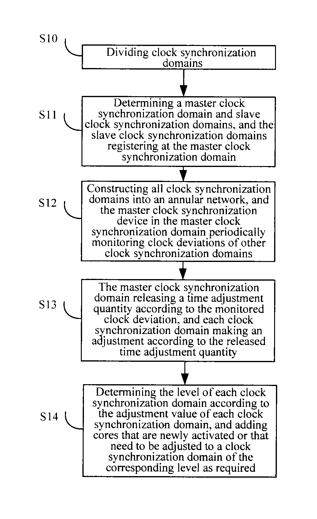
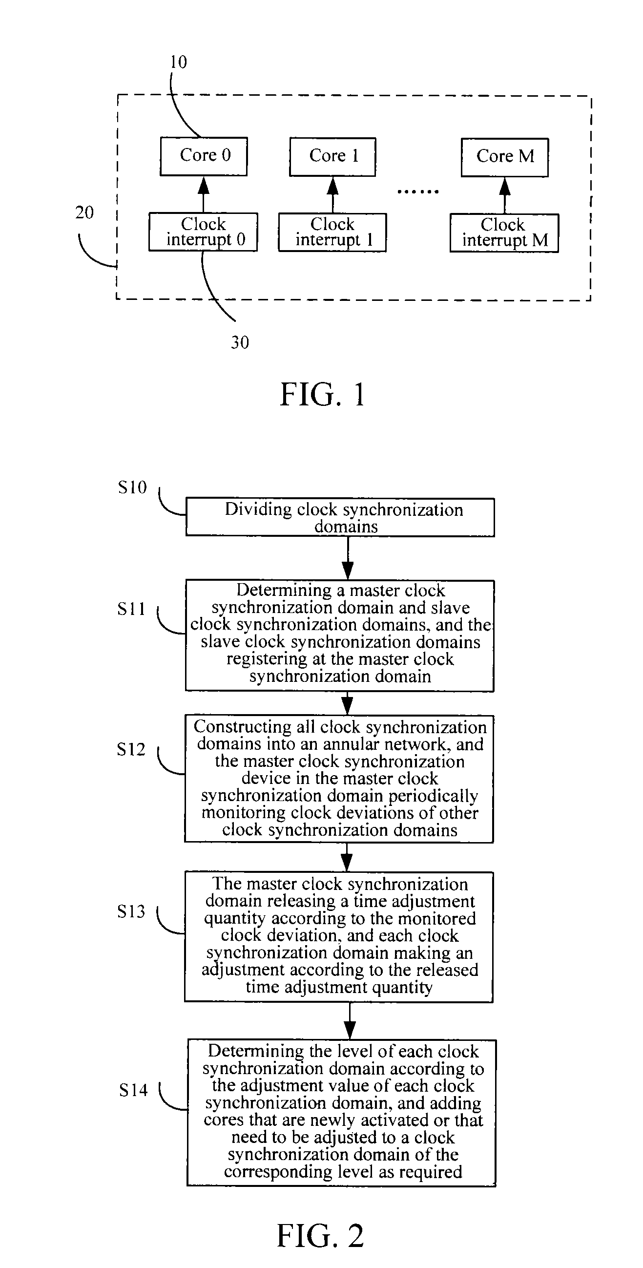
[0041]Specific embodiments of the present invention are shown in FIGS. 2-5, and as shown in FIG. 2, the time synchronization method according to a specific embodiment of the present invention mainly comprises the following steps:

[0042]S10, firstly dividing clock synchronization domains, and uniquely allocating each core to each clock synchronization domain;

[0043]S11, determining a master clock synchronization domain and slave clock synchronization domains, and the slave clock synchronization domains sending a registering message to the master clock synchronization domain;

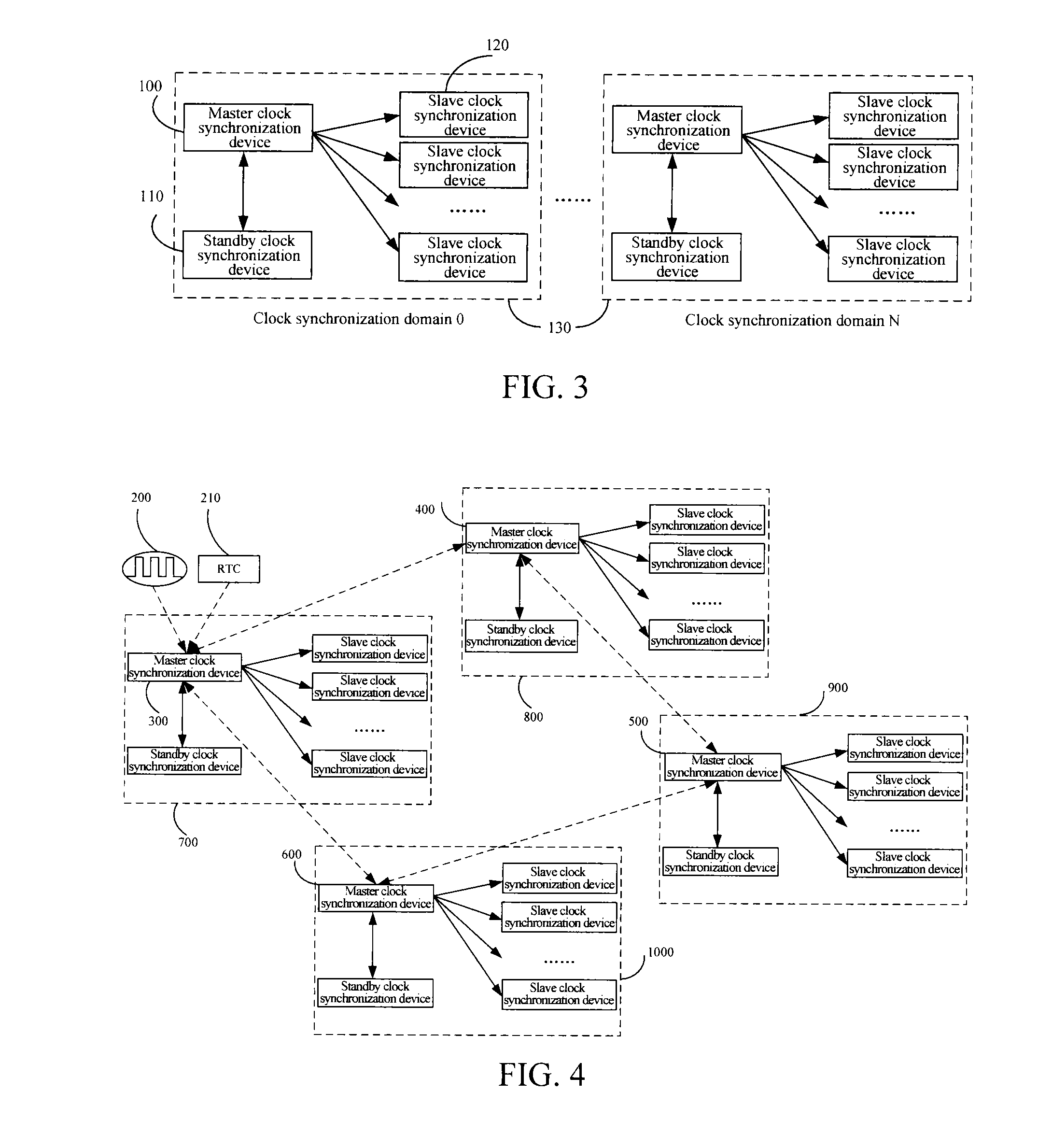
[0044]S12, constructing all clock synchronization domains into an annular network, and the master clock synchronization device of the master clock synchronization domain periodically monitoring clock deviations of other clock synchronization domains;

[0045]S13, when it is necessary to make an adjustment, ...


PUM


Abstract

A time synchronization method and system for a multi-core system are provided. The time synchronization method comprises: establishing at least one clock synchronization domain, and respectively allocating each core to each clock synchronization domain; selecting a core with a lowest load in each clock synchronization domain as a master clock synchronization source in the clock synchronization domain, and selecting the clock synchronization domain having the master clock synchronization source with a lowest load as a master clock synchronization domain, while other clock synchronization domains as slave clock synchronization domains; the master clock synchronization domain sending a synchronization deviation detection message to each slave clock synchronization domain, and calculating a time deviation value; when the time deviation value is greater than a permitted deviation value, the master clock synchronization domain calculating a time adjustment quantity and releasing to each slave clock synchronization domain, making adjustment based on its time adjustment quantity.

Description

CROSS REFERENCE RELATED APPLICATIONS[0001]This application is a national phase of PCT / CN2009 / 073574 filed Aug. 27, 2009 which claims priority to China Application Serial No. 200810142169.5, filed Sep. 2, 2008, both of which are entirely incorporated herein by reference.TECHNICAL FIELD[0002]The present invention relates to the field of multi-core processor, and in particular, to a time synchronization method and system for a multi-core system.BACKGROUND ART[0003]Generally, only a single embedded operating system can be operated in a single-core embedded processor system, and during operation of the system, the most crucial system clock interrupt is implemented by converting the time interval of timer interrupt into a specific value, submitting the timer interrupt to the core when the number of a core hardware counter accumulates up to the value of the time interval, and automatically re-loading the counter by the processor; considering that the interval of the timer interrupt should ...

Claims


Application Information

Patent Timeline
Patent Type & Authority Patents(United States)
IPC IPC(8): G06F13/42G06F1/12
CPCG06F1/14
Inventor ZHAO, YANGXIAO, LI
Owner ZTE CORP
Learn More