
Tag label producing apparatus

a label and label technology, applied in the direction of mechanical control devices, instruments, process and machine control, etc., can solve the problems of little consideration of the adverse effects of pressing force on the communication, the risk of a drop in etc., to prevent the occurrence of communication errors and improve the reliability and stability of communication

Active Publication Date: 2013-01-29
BROTHER KOGYO KK
View PDF13 Cites 0 Cited by
  • Summary
  • Abstract
  • Description
  • Claims
  • Application Information

AI Technical Summary

Benefits of technology

[0009]An object of the present disclosure is to provide a tag label producing apparatus capable of improving reliability and stability of communication during RFID label production.
[0011]When providing the RFID circuit element to the tag medium, in general, an IC circuit part and a tag antenna connected to the IC circuit part are provided in a laminated structure including a tape-like or sheet-like substrate, an adhesive agent, and the like. Since a contact point between the IC circuit part and the tag antenna is present in the laminated structure, it is preferable to perform communication with no external pressing force applied to the laminated structure including the contact point, from the point of view of ensuring reliability and stability of communication.
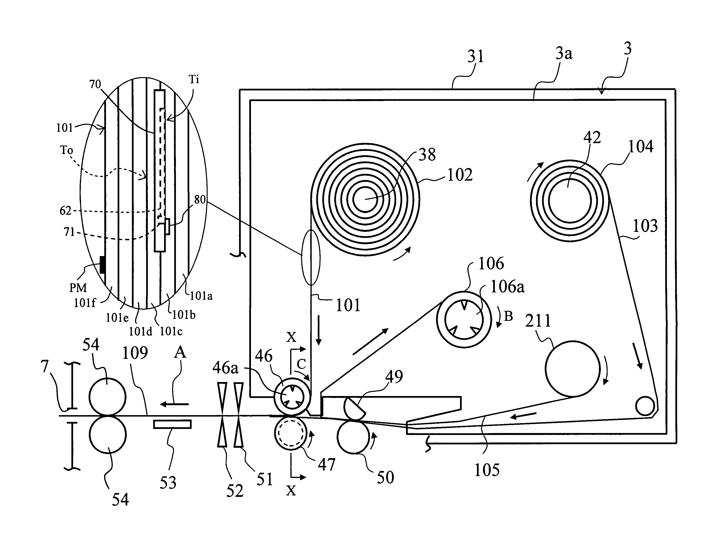
[0013]It is thus possible to perform communication between the apparatus antenna and the RFID circuit element after the contact point between the IC circuit part and the tag antenna has been subjected to the pressing force by the last nearest roller (before communication), and after the effects of the pressing force by the nearest roller have disappeared as sufficient time has passed. Accordingly, it is possible to improve the reliability and stability of communication during production of RFID labels and prevent occurrences of communication errors.

Problems solved by technology

However, in a case in which wireless communication is performed before sufficient time has passed since passing through the nearest roller, the effects of the pressing force on the contact of the RFID circuit element have not disappeared, and there is a risk of a drop in reliability and stability of communication due to some kind of residual effects on the communication characteristics.
With the prior art described above, particularly little consideration has been given to the adverse effects by the pressing force on the communication characteristics of the RFID circuit elements during tag label production in this way.

Method used


Image

  • Tag label producing apparatus
  • Tag label producing apparatus
  • Tag label producing apparatus

Examples


Embodiment Construction

[0028]An embodiment of the present disclosure is described below with reference to the drawings.

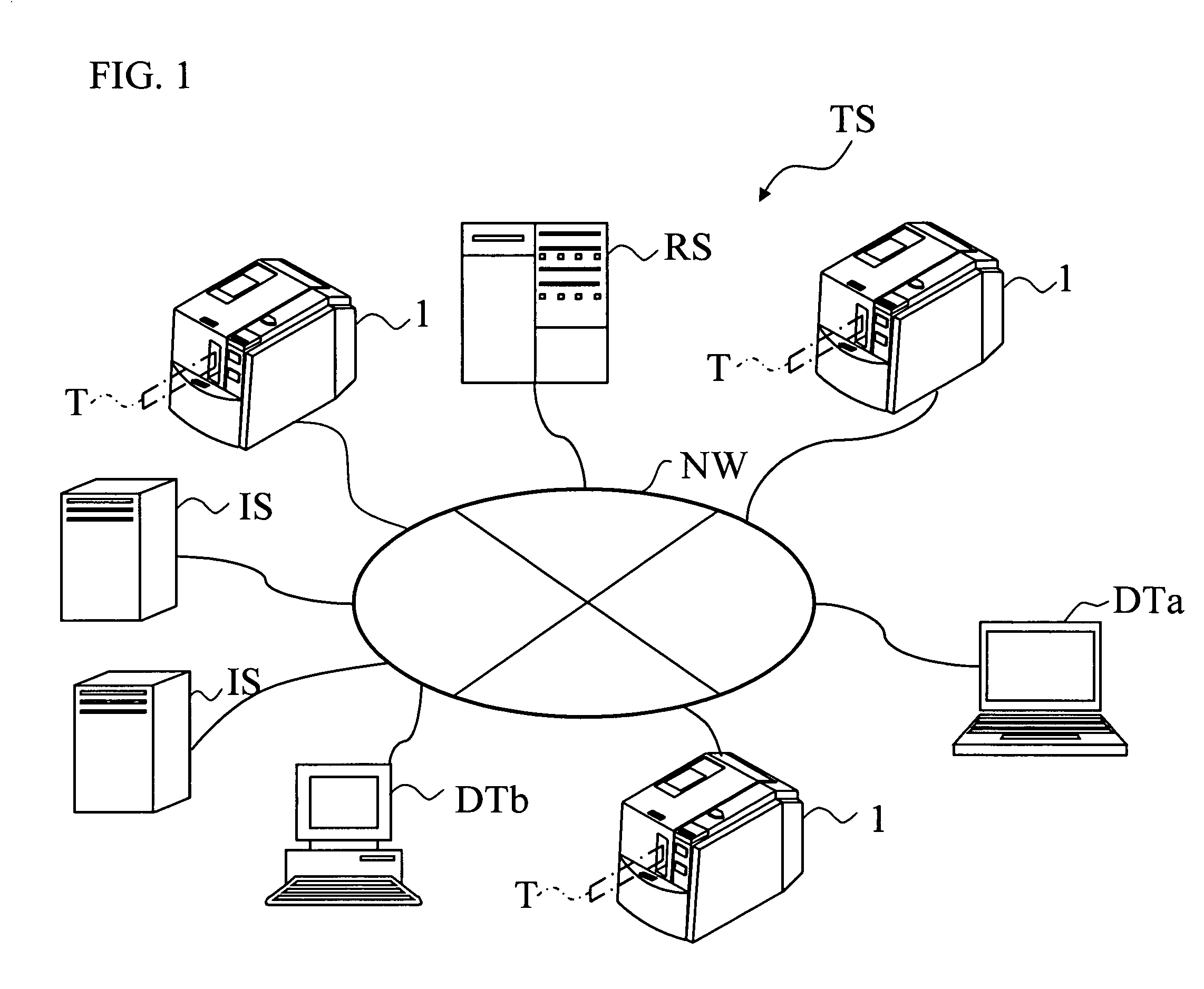
[0029]In this RFID label system TS shown in FIG. 1, the tag label producing apparatus 1 according to the present embodiment is connected to a root server RS, an information server IS, a terminal device DTa, a general purpose computer DTb, and so on, via a communication network NW made up of appropriate communication lines and so on.

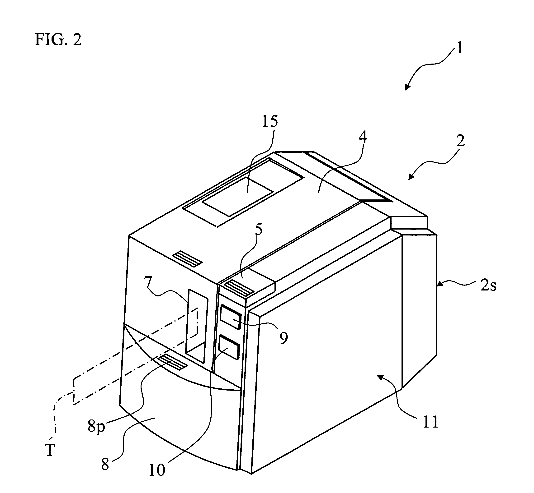
[0030]As shown in FIG. 2, an apparatus body 2 (comprising a top face part, a bottom face part, a front fact part, a rear face part, and left and right side parts) of the tag label producing apparatus 1 is provided with an overall rectangular cubical housing 2s as an outer shell. A top lid 4 and a top lid manipulating button 5 are provided to the top face part. A label discharge opening 7, a front lid 8, a power button 9, and a cutter driving button 10 are provided to the front face part.

[0031]The top lid 4 is rotatably supported at a right back edge in FIG. 2 o...


PUM

PropertyMeasurementUnit
speedaaaaaaaaaa
areaaaaaaaaaaa
distanceaaaaaaaaaa

Abstract

This disclosure discloses a tag label producing apparatus comprising: at least one feeding roller; a printing device; and an apparatus antenna; and a coordination control portion that controls in coordination the feeding roller, the printing device, and the apparatus antenna, such that information transmission / reception is performed between an RFID circuit element and the apparatus antenna when an IC circuit part of the RFID circuit element provided to a tag medium is fed downstream in a transport direction from a segment from a nearest roller to the apparatus antenna along a feeding path.

Description

CROSS-REFERENCE TO RELATED APPLICATIONS[0001]This application claims priority from JP 2007-202661, filed Aug. 3, 2007, the contents of which are hereby incorporated by reference.BACKGROUND[0002]1. Field[0003]The present disclosure relates to a tag label producing apparatus that produces RFID labels comprising RFID circuit elements capable of transmitting and receiving information through wireless communication.[0004]2. Description of the Related Art[0005]RFID (Radio Frequency Identification) systems that perform reading / writing between a compact RFID tag and a reader / writer (reading / writing apparatus) in a non-contact manner are known. For example, an RFID circuit element provided to a label-shaped RFID tag (RFID label) comprises an IC circuit part that stores predetermined RFID tag information, and a tag antenna that is connected to the IC circuit part and transmits and receives information. With such an arrangement, the reader / writer can access (read / write) the RFID tag informatio...

Claims


Application Information

Patent Timeline
Patent Type & Authority Patents(United States)
IPC IPC(8): B32B41/00
CPCB41J3/4075B41J3/50
Inventor FUKUI, TOMOYASUNAGAE, TSUYOSHIOHTA, KIYOICHIHIOKI, HITOMITOMITA, SHINTARO
Owner BROTHER KOGYO KK
Learn More