
Low energy laser-induced ignition of an air-fuel mixture

a low-energy laser and air-fuel technology, applied in the field of photoionization, can solve problems such as engine failur

Active Publication Date: 2014-10-14
AIR FORCE UNITED STATES OF AMERICA AS REPRESETED BY THE SEC OF THE THE
View PDF16 Cites 6 Cited by
  • Summary
  • Abstract
  • Description
  • Claims
  • Application Information

AI Technical Summary

Benefits of technology

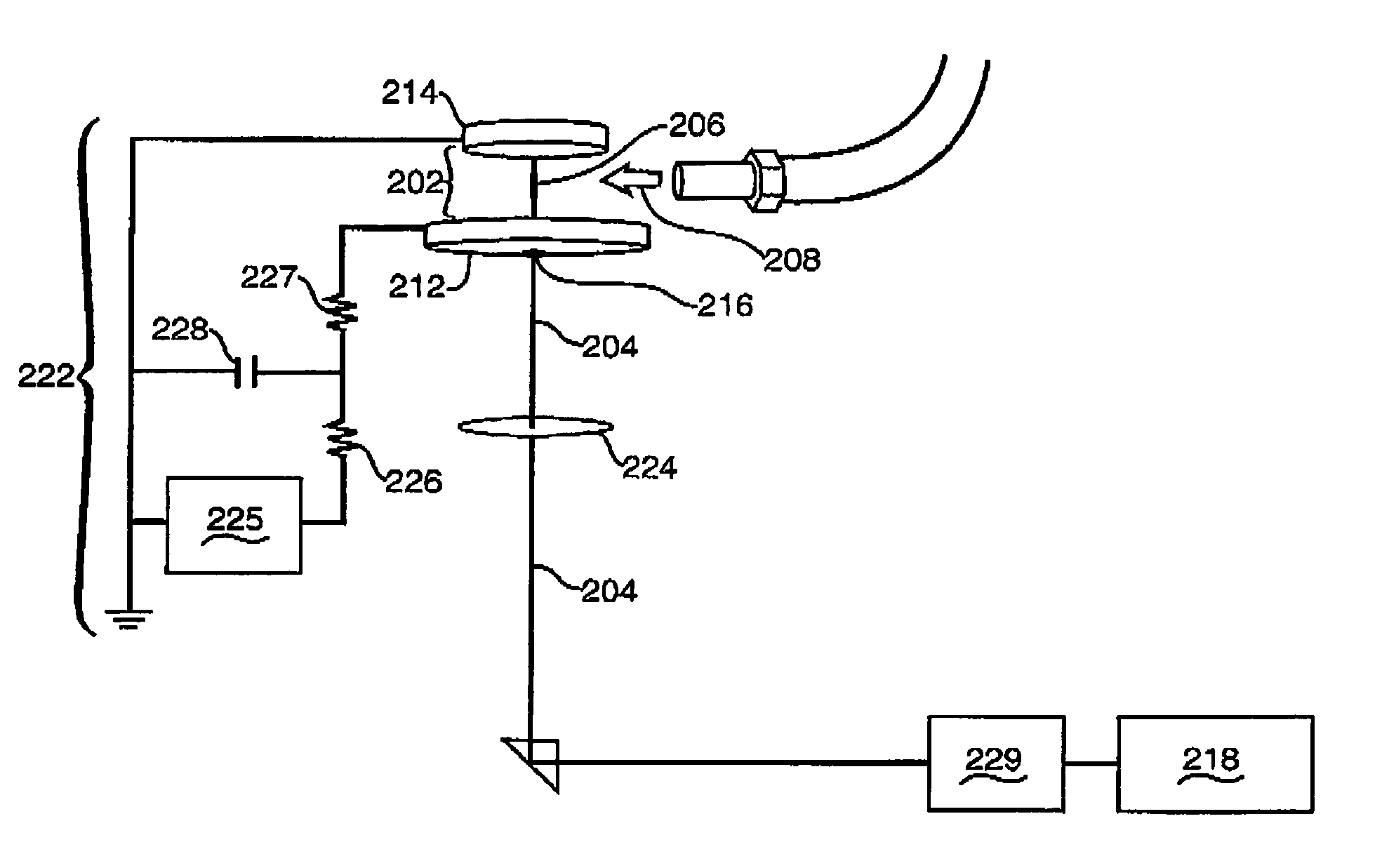
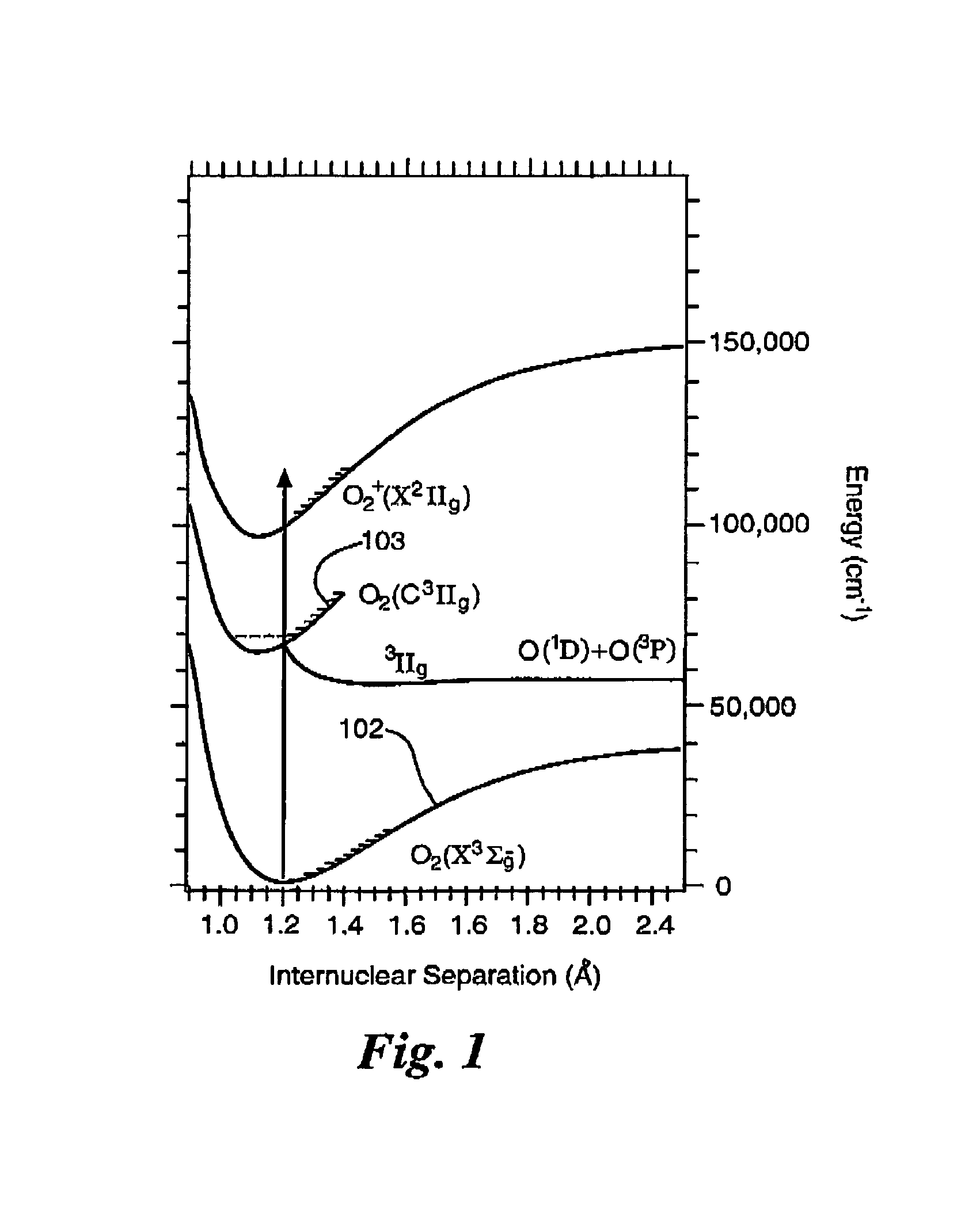
The present invention uses a low energy ultraviolet laser to create a pre-ionized channel in a combustion chamber, allowing a smaller voltage electric field to create an electrical arc or spark that follows the pre-ionized channel. This eliminates the need for electrodes inside the combustion chamber and allows the arc to be directed to an optimal location for igniting the air-fuel mixture. The laser wavelength is tailored to optimize excitation to a specific molecular oxygen state that is coincident in energy with a metastable molecular nitrogen state in atmospheric air, maximizing the subsequent photoionization efficiency. The technical effect is to improve the efficiency and control of ignition in combustion engines.

Problems solved by technology

As described in U.S. Pat. No. 5,673,550 to Few et al, “spark igniters are typically positioned at a peripheral, non-optimal position of a combustion chamber, while the fuel spray to be ignited is located in a central portion adjacent to a fuel injector.” As also described in the Few et al. patent, spark igniters will degrade over time and can cause engine failure.
Unfortunately, as described in that prior art, present art laser igniters typically require very high power pulsed lasers to create a high-field breakdown of air and photoelectric effects at an electrode surface.
The primary unrealized goal of the prior art has been to be able to create an ionized channel using a low energy source.
A related unrealized goal of the prior art has been a laser igniter that can guide a lower power laser pulse through a fiber optic cable into an ignition region and still reliably induce ignition of an air-fuel mixture.

Method used


Image

  • Low energy laser-induced ignition of an air-fuel mixture
  • Low energy laser-induced ignition of an air-fuel mixture
  • Low energy laser-induced ignition of an air-fuel mixture

Examples


Embodiment Construction

[0025]The resonant laser-induced ignition concept of the present invention uses a relatively low energy ultraviolet laser pulse to efficiently induce volume ionization in atmospheric air using a laser tuned to the proper wavelength to achieve resonant-enhanced multiphoton ionization (REMPI). The induced breakdown of an air gap with a novel ultraviolet laser triggering scheme according to the teachings of the present invention provides both spatial and temporal precision to a resulting electrical arc.

[0026]The teachings of the present invention are also described in Stephen F. Adams, Jared A. Miles and Adam C. Laber, Resonant Laser Induced Breakdown for Fuel Air Ignition, AIAA 2010-646, 48th AIAA Aerospace Sciences Meeting, 4-7 Jan. 2010, Orlando, Fla., which is incorporated by reference into this description.

[0027]Key to the example embodiment of the laser excitation approach of the present invention illustrated in this detailed description is the use of a focused pulsed laser near ...


PUM


Abstract

A new approach for igniting an air-fuel mixture in a turbine or other engine is disclosed. Resonance-enhanced multiphoton ionization (REMPI) is used to generate volume ionization within an air-fuel flow and induce an ignition arc. The output of a relatively low energy single pulsed ultraviolet laser is aimed across an electric field inside a volume of air to create a pre-ionized channel so that a smaller voltage electric field is sufficient to create an electrical arc that follows the pre-ionized channel and will ignite an air-fuel mixture. Because the arc follows the pre-ionized channel, it can be directed to an optimal location inside an ignition volume for igniting the air-fuel mixture. A specific example embodiment is described using a 287.5 nm wavelength pulsed ultraviolet laser to excite ground state oxygen molecules to a specific excited state having a coincident term energy with a specific nitrogen molecule excited state.

Description

RIGHTS OF THE GOVERNMENT[0001]The invention described herein may be manufactured and used by or for the Government of the United States for all governmental purposes without the payment of any royalty.BACKGROUND OF THE INVENTION[0002]The present invention relates generally to photoionization, and more particularly to using a single pulsed ultraviolet laser to ionize an air-fuel mixture to improve ignition of gas turbine and other engines.[0003]Gas turbine and other engines require igniting an air-fuel mixture, generally in a combustion chamber section of the engine. Most prior art gas turbine igniters work by generating high tension electrical sparks, or arcs, across a pair of electrodes. The sparks are triggered by a very high voltage electric field across the electrodes generated by conventional induction coils or by other methods.[0004]As described in U.S. Pat. No. 5,673,550 to Few et al, “spark igniters are typically positioned at a peripheral, non-optimal position of a combusti...

Claims


Application Information

Patent Timeline
IPC IPC(8): F23N5/20
CPCF23N2027/28F23N5/20F23C99/00F23C2900/99003F23R2900/00006F23Q13/005F23N2227/28
Inventor ADAMS, STEVEN, F.
Owner AIR FORCE UNITED STATES OF AMERICA AS REPRESETED BY THE SEC OF THE THE
Learn More