
Ultra-low noise VCO

a low noise, ultra-low technology, applied in the direction of pulse generator, pulse technique, electrial characteristics varying frequency control, etc., can solve the problems of reducing power at the desired frequency, noise sideband, inherent noise source of vco, etc., and achieve high levels of phase noise cancellation

Active Publication Date: 2014-09-09
SCI COMPONENTS
View PDF21 Cites 5 Cited by
  • Summary
  • Abstract
  • Description
  • Claims
  • Application Information

AI Technical Summary

Benefits of technology

The present invention provides an ultra-low phase noise voltage controlled oscillator (VCO) that can be easily fabricated from discrete components onto a small pc board. The VCO includes a resonant circuit and an active circuit with a negative feedback path, which cancels out phase noise and reduces odd harmonics output. The negative feedback path includes a series of negative feedback elements, such as capacitors and inductors, that work together to minimize phase noise. The resonant circuit has a plurality of capacitors and a varactor diode to control the resonant frequency. Overall, the present invention provides a compact, highly efficient and reliable pieced based VCO for use in various electronic devices.

Problems solved by technology

As with any electronic device, a VCO has inherent noise sources.
Phase noise is undesirable because the phase noise components of a signal at a desired frequency spread the power of the signal to adjacent frequencies, resulting in noise sidebands and reducing power at the desired frequency.
However, the disadvantage of this VCO is that the additional capacitances thereof limit the application at high frequencies as the capacitances may result in the cessation of oscillation.
Additionally, use at high frequencies may be limited because when more transistors are required more pads are required with the concomitant result of increasing parasitic effects.
Additionally, no quantitative information is disclosed as to the actual degree of phase noise reduction provided by this circuit, thus leaving the actual degree of benefit unknown.
Further, the component matching requirements of this circuit certainly would require it to be implemented only as an integrated circuit, rather than having the option of implementing it with discrete components.
Additionally, the component matching requirements of this circuit certainly would require it to be implemented only as an integrated circuit, rather than having the option of implementing it with discrete components.
The resonant circuit and the active circuit in combination function as an oscillator circuit wherein phase noise present at the negative feedback node is fed at opposite phase back to the transistor input node, providing extremely high levels of phase noise cancellation.

Method used


Image

  • Ultra-low noise VCO
  • Ultra-low noise VCO
  • Ultra-low noise VCO

Examples


Embodiment Construction

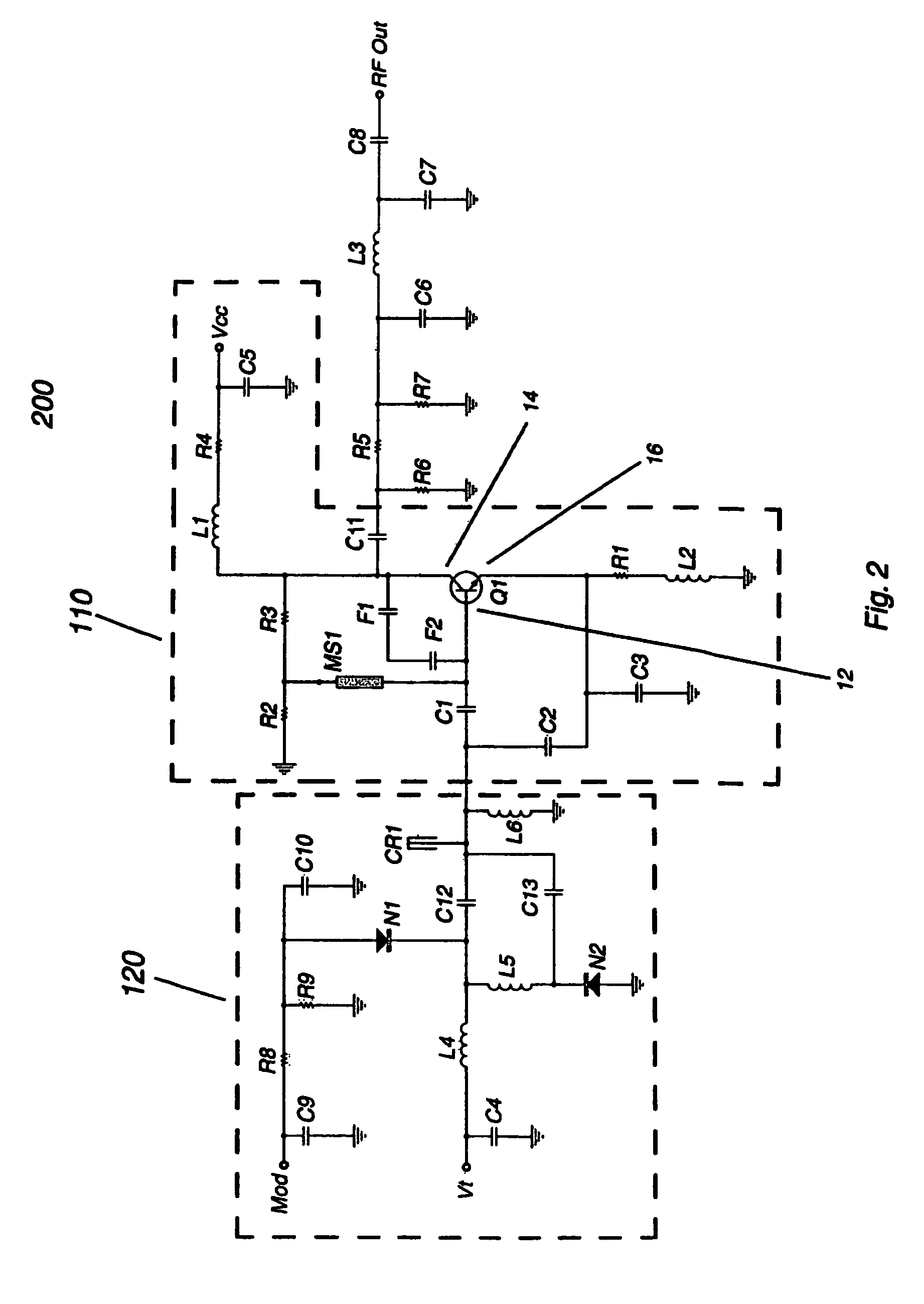
[0027]FIG. 1 shows a basic oscillator circuit 10 comprising a Colpitts oscillator based on a single bipolar transistor Q1, having an input node 12, a negative feedback path 14 and a positive feedback path 16. DC biasing is provided by resistors R1, R2 and R3. Capacitor C2 provides the positive feedback path, and in combination with C1, C3 and resonant circuit portion 20 provides the resonance circuit for the oscillator. Inductor L1 is the RF choke and capacitor C5 is an output coupling capacitor. In the preferred embodiment the negative feedback element F1 is a capacitor, and the negative feedback element F2 is an inductor. Negative feedback elements F1 and F2 in series form the negative feedback network. In use, either F1 or F2 can be the capacitor and the other negative feedback element can be either a capacitor, inductor, resistor or even just a shorting connection. Transistor Q1 can be supplemented with multiple transistors in parallel to increase power output.

[0028]When a capac...


PUM


Abstract

An ultra-low phase noise voltage controlled oscillator uses a single bipolar transistor Colpitts oscillator circuit and a noise-reducing negative feedback path consisting of a capacitor and a second element which may be a second capacitor, an inductor or a resistor. The negative feedback path is kept separate from any DC biasing paths in the circuit. A pair of varactor diodes are used to provide resonant frequency control.

Description

BACKGROUND OF THE INVENTION[0001]1. Field of the Invention[0002]The present invention relates generally to voltage controlled oscillators (VCOs) and more particularly to a VCO using a single transistor Colpitts oscillator circuit and having a negative feedback network configured to provide ultra-low phase noise.[0003]2. Description of the Prior Art[0004]A VCO is an electronic circuit with an oscillator having a frequency control input whereby a control voltage can vary the frequency of oscillation. Numerous types of oscillators can be used in VCOs, each with specific advantages and constraints. VCOs often serve as building blocks for more complex circuits, including phase-locked loops and voltage-to-frequency converters. VCOs and circuits incorporating them are used in cellphones and other radio communication devices, and with ever-increasing demands for wireless device performance are subject to ever-increasing requirements for performance and efficiency.[0005]The oscillator circui...

Claims


Application Information

Patent Timeline
Patent Type & Authority Patents(United States)
IPC IPC(8): H03K3/282
CPCH03B5/1231H03B2200/009H03B2202/073H03B5/1243H03K3/282H03B5/1203H03B2200/0008
Inventor GAMLIEL, DORON
Owner SCI COMPONENTS
Learn More