Contact element for an electrically conductive connection between an anode and an interconnector of a high-temperature fuel cell

a technology of contact element and fuel cell, which is applied in the direction of fuel cell, solid electrolyte fuel cell, cell components, etc., can solve the problems of thermal expansion, contact can be ripped off, and the contacting of the cathode is subject to tensile strain, so as to achieve more reliable electrically conductive connection and long-term stability

Active Publication Date: 2014-09-09
FRAUNHOFER GESELLSCHAFT ZUR FOERDERUNG DER ANGEWANDTEN FORSCHUNG EV
View PDF15 Cites 0 Cited by
  • Summary
  • Abstract
  • Description
  • Claims
  • Application Information

AI Technical Summary

Benefits of technology

The invention aims to create a stronger and more stable electrically conductive connection between the anode of a high-temperature fuel cell and the interconnector. This is achieved by using deformation during cooling down from the operating temperature, where peaks and troughs are formed on the surface of the contact element. These changes in deformation lead to improved electrical contact between the regions of the contact element.

Problems solved by technology

A further problem which generally has to be taken into account with high-temperature fuel cells is the thermal expansion, due to the high operating temperature of the fuel cells.
This has the result that a ceramic contacting of the cathode is subject to tensile strains and the contact can tear off there.
A reduction in the thickness of such an electrically conductive connection formed with nickel in this manner between the anode and the interconnector is also not expedient since mechanical strains and production tolerances must also be compensated by the ductility of the nickel.
This has a particularly disadvantageous effect on the restarting of a previously deenergized fuel cell since no such contact is present at a current collector formed in this manner at least during this time via which a large electric current can flow locally restricted in this manner between the anode and the interconnector.

Method used


Image

  • Contact element for an electrically conductive connection between an anode and an interconnector of a high-temperature fuel cell
  • Contact element for an electrically conductive connection between an anode and an interconnector of a high-temperature fuel cell
  • Contact element for an electrically conductive connection between an anode and an interconnector of a high-temperature fuel cell

Examples


Embodiment Construction

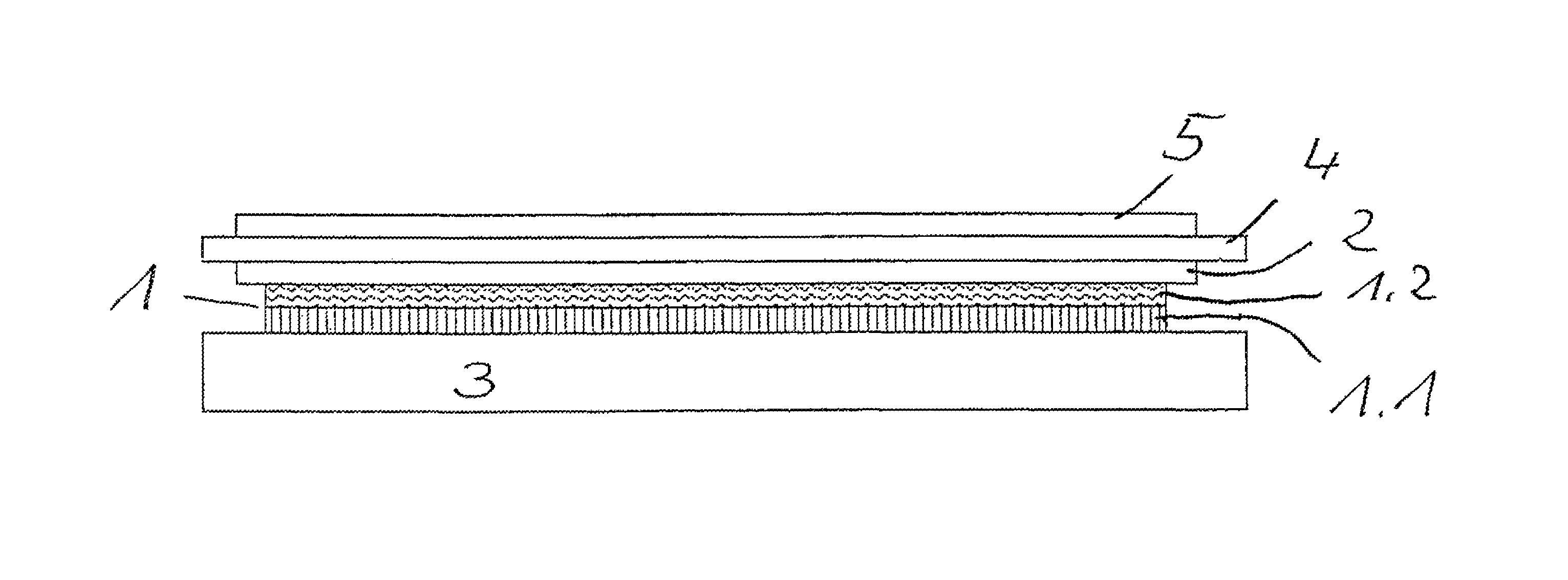
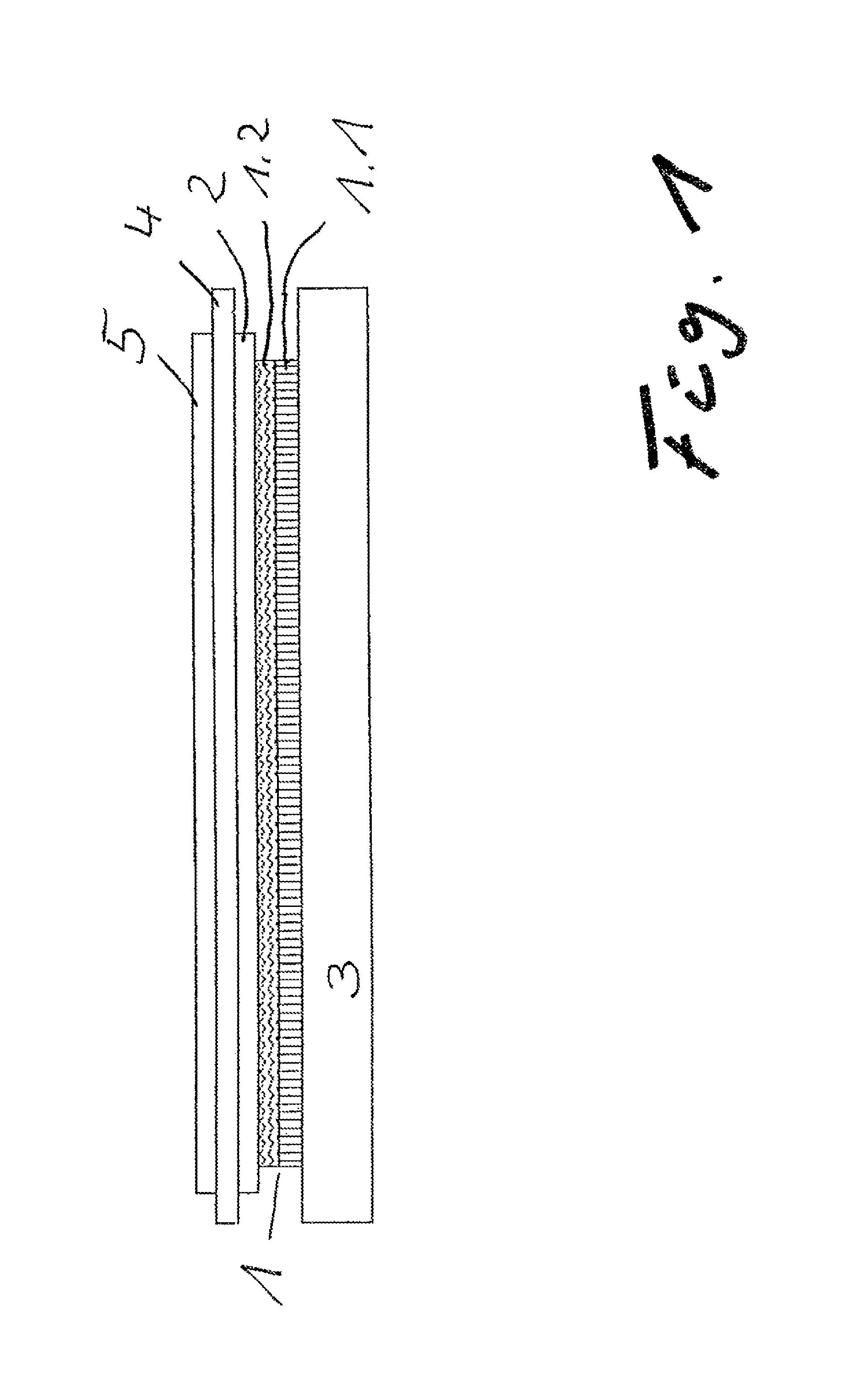
[0034]A high-temperature fuel cell is shown in section in FIG. 1. In this respect, a contact element 1 on an interconnector 3 is arranged between it and the anode 2. The solid electrolyte 4 and a cathode 5 are arranged above the anode 2.

[0035]The contact element 1 is here formed with two films as the two part elements 1.1 and 1.2. In this respect, the part element 1.1 arranged at the interconnector side is formed from pure copper (α=16.5*10−3 K−1 at 20° C.) and it has a thickness of 290 μm. The second part element 1.2 arranged at the anode side is formed with a 120 μm thick film of pure nickel (α=13.0*10−3 K−1 at 20° C.)


PUM


Abstract

The invention relates to a contact element for an electrically conductive connection between an anode and an interconnector of a high-temperature fuel cell. It is the object of the invention to achieve a more reliable electrically conductive connection with long-term stability between an anode and the associated interconnector of a high-temperature fuel cell. The contact element in accordance with the invention is arranged between an anode and an interconnector of a high-temperature fuel cell. It is formed with two areal electrically conductive part elements. In this respect, one respective part element is in touching contact with the anode and the other part element is in touching contact with the respective interconnector. Openings are formed in the part elements and the part elements are formed from materials having mutually different coefficients of thermal expansion.

Description

BACKGROUND[0001]The invention relates to a contact element for an electrically conductive connection between an anode and an interconnector of a high-temperature fuel cell. With high-temperature fuel cells, it is customary to combine individual fuel cells to stacks and to connect them to one another in an electrically conductive manner in so doing. For this purpose, interconnectors, which are also called bipolar plates, are arranged between the electrodes of individual fuel cells. The electric current can thus flow from one electrode of a fuel cell to the oppositely poled electrode of the proximate fuel cell.[0002]Since it is, however, necessary that fuel or oxidizing agent can move to the electrodes, a permeability or porosity is required for this purpose, which influences the electrical conductivity.[0003]Differently configured current collectors have thus previously been used between the electrodes and the respectively arranged interconnectors. Examples for this are networks or c...

Claims


Application Information

Patent Timeline
IPC IPC(8): H01M8/02H01M8/12
CPCH01M8/0232H01M8/0245Y02E60/50Y02E60/525H01M2008/1293
Inventor WAESCHKE, ULFKUSNEZOFF, MIHAILS
Owner FRAUNHOFER GESELLSCHAFT ZUR FOERDERUNG DER ANGEWANDTEN FORSCHUNG EV
Why Eureka
Try Eureka