
Thermoplastic compositions for laser direct structuring and methods for the manufacture and use thereof

a technology of thermoplastic compositions and laser direct structure, which is applied in the direction of transportation and packaging, energy-based chemical/physical/physical-chemical processes, chemical/physical/physical-chemical processes, etc., can solve the problems of high tooling cost, high cost and time-consuming modification of tooling, and the limitation of the pattern geometry of stamping and fpcb mounted processes

Active Publication Date: 2014-08-26
SHPP GLOBAL TECH BV
View PDF20 Cites 11 Cited by
  • Summary
  • Abstract
  • Description
  • Claims
  • Application Information

AI Technical Summary

Benefits of technology

[0025]Other advantages will be set forth in part in the description which follows or may be learned by practice. The advantages will be realized and attained by means of the elements and combinations particularly pointed in the appended claims. It is to be understood that both the foregoing general description and the following detailed description are exemplary and explanatory only and are not restrictive, as claimed.

Problems solved by technology

However, stamping and FPCB mounted process have limitations in the pattern geometry, and the tooling is expensive.
Also, altering of a RF pattern causes high-priced and time-consuming modifications in tooling.
This method involves relatively high initial costs and is only economically viable for large production numbers.
2-shot-molding is also not regarded as an environmentally friendly process.
All of these three methods are tool-based technologies, which have limited flexibility, long development cycles, difficult prototype, expensive design changes, and limited ability to produce miniaturization.
In addition, some LDS fillers have a surface pH that may be detrimental to the polymer matrix during processing, resulting in degradation of the polymers.
This polymer matrix degradation leads to, for example, decreased ductility for the final composition.
The changed ductility, along with and other property changes, may result in substantial, and potentially undesirable, changes in the material's overall properties.

Method used

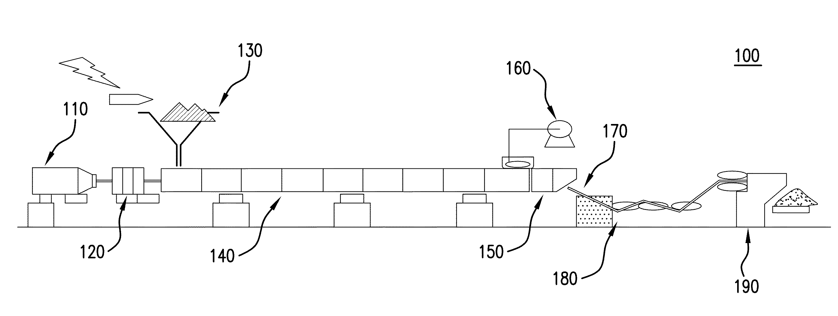
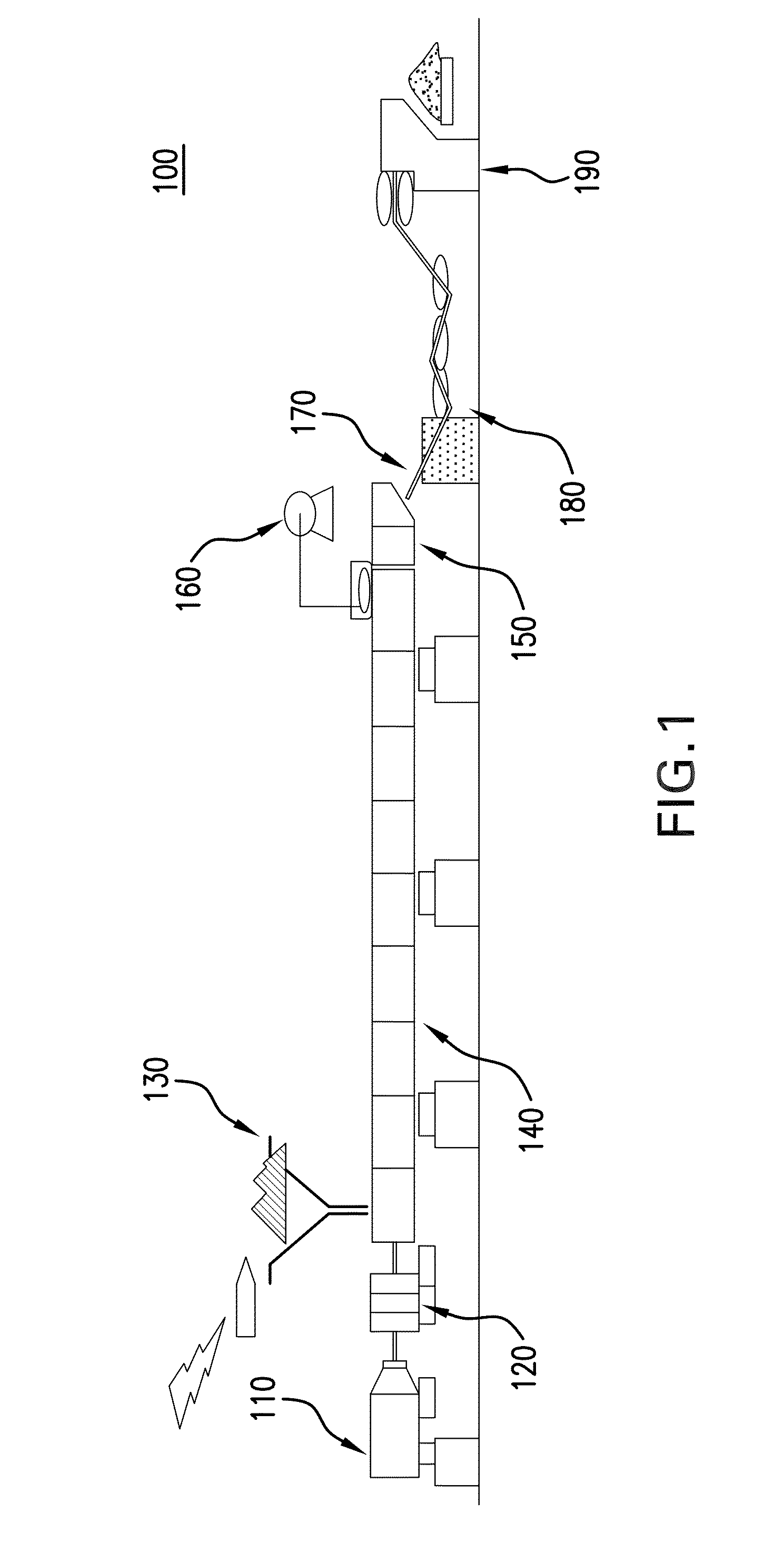
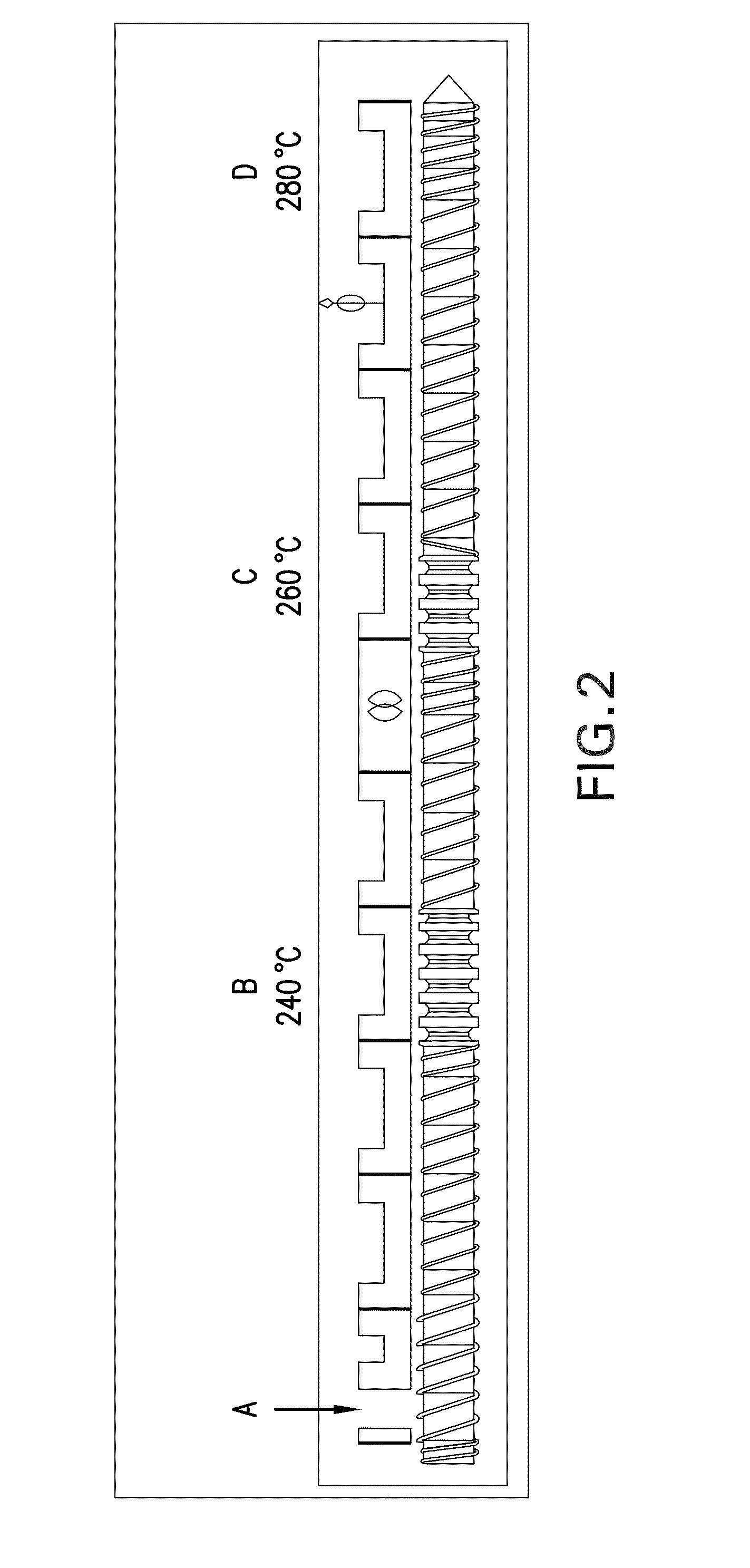

Image

  • Thermoplastic compositions for laser direct structuring and methods for the manufacture and use thereof
  • Thermoplastic compositions for laser direct structuring and methods for the manufacture and use thereof
  • Thermoplastic compositions for laser direct structuring and methods for the manufacture and use thereof

Examples


examples

[0268]The following examples are put forth so as to provide those of ordinary skill in the art with a complete disclosure and description of how the methods, devices, and systems disclosed and claimed herein are made and evaluated, and are intended to be purely exemplary and are not intended to limit the disclosure. Efforts have been made to ensure accuracy with respect to numbers (e.g., amounts, temperature, etc.), but some errors and deviations should be accounted for. Unless indicated otherwise, parts are parts by weight, temperature is in degrees Celsius (° C.) or is at ambient temperature, and pressure is at or near atmospheric.

General Materials and Methods

[0269]For the non-limiting Examples described herein below, sample compositions were prepared from the components described in Table 1 below. The Example compositions (labeled as “Example 1,”“Example 2,” and the like) and various comparator samples (labeled as “Comp. 1,”“Comp. 2,” and the like) are further described herein. M...


PUM

PropertyMeasurementUnit
thicknessaaaaaaaaaa
weight %aaaaaaaaaa
conductive path widthsaaaaaaaaaa

Abstract

The present disclosure relates to thermoplastic compositions. The disclosed compositions comprise a polycarbonate polymer, a polysiloxane-polycarbonate copolymer, a laser direct structuring additive, and a siloxane additive. Also disclosed are methods for making the disclosed thermoplastic compositions and articles of manufacture comprising the disclosed thermoplastic compositions.

Description

BACKGROUND OF THE INVENTION[0001]Electrical components can be provided as molded injection devices (MID) with desired printed conductors. In contrast to conventional circuit boards made of fiberglass-reinforced plastic or the like, MID components manufactured in this way are three-dimensional (3D) molded parts having an integrated printed conductor layout and possibly further electronic or electromechanical components. The use of MID components of this type, even if the components have only printed conductors and are used to replace conventional wiring inside an electrical or electronic device, saves space, allowing the relevant device to be made smaller. It also lowers the manufacturing costs by reducing the number of assembly and contacting steps. These MID devices have great utility in cell phones, PDAs and notebook applications.[0002]Stamp metal, flexible printed circuit board (FPCB) mounted and two-shot molding methods are three existing technologies to make an MID. However, st...

Claims


Application Information

Patent Timeline
Patent Type & Authority Patents(United States)
IPC IPC(8): C08F283/00C08F283/02B01J19/12
CPCC08L83/10C08L69/00C08G77/26C08K3/22C08K5/5415C08L83/00C08K2003/2251
Inventor GANGULY, ANIRBANMITRA, SUSANTATONG, WUSHUIPING, LIU
Owner SHPP GLOBAL TECH BV
Learn More