
Method in which a relay allocates carriers on a backhaul link and an access link in a multi-carrier wireless communication system

a wireless communication system and relay technology, applied in multiplex communication, orthogonal multiplex, frequency division multiplex, etc., can solve the problem of not being able to allocate a frequency having a broad band all around the world, and achieve efficient multiplexing, efficient configuration and assignment, and the effect of preventing transmission and reception collision between the backhaul link and the access link

Inactive Publication Date: 2014-08-19
LG ELECTRONICS INC
View PDF9 Cites 15 Cited by
  • Summary
  • Abstract
  • Description
  • Claims
  • Application Information

AI Technical Summary

Benefits of technology

[0026]According to the present invention, multiple carriers can be efficiently configured for and assigned to a backhaul link and an access link and the backhaul link can be efficiently multiplexed with the access link. In addition, transmission and reception collision between the backhaul link and the access link can be prevented during a transmission feedback operation.
[0027]It will be appreciated by persons skilled in the art that that the effects that could be achieved with the present invention are not limited to what has been particularly described hereinabove and other advantages of the present invention will be more clearly understood from the following detailed description.

Problems solved by technology

However, it is not easy to allocate a frequency having a broad band all around the world except some regions.

Method used


Image

  • Method in which a relay allocates carriers on a backhaul link and an access link in a multi-carrier wireless communication system
  • Method in which a relay allocates carriers on a backhaul link and an access link in a multi-carrier wireless communication system
  • Method in which a relay allocates carriers on a backhaul link and an access link in a multi-carrier wireless communication system

Examples


embodiment 1

[0180

[0181]Referring to FIG. 9, it is assumed that backhaul and access downlink subframes are configured on DL CC0, backhaul, backhaul and access uplink subframes corresponding to the backhaul and access downlink subframes are configured on UL CC0, and backhaul downlink subframes 911, 912, 913 and 914 or backhaul uplink subframes 921, 922, 923 and 924 are allocated every 10 ms in relation to the above-described HARQ timing.

[0182]Meanwhile, without introduction of RNs, a synchronous non-adaptive HARQ operation with an 8-ms period (a Round Trip Time (RTT) of 8 ms) as defined in the legacy LTE system is performed for a legacy UE (e.g. an LTE Release-8 UE). For example, upon receipt of an access uplink signal from a UE on UL CC0 (931), an RN transmits an HARQ feedback on DL CC0, 4 TTIs later (912). The downlink subframe 912 is an MBSFN subframe in which an HARQ feedback can be transmitted to the UE on a PHICH included in the first two OFDM symbols. If the HARQ feedback is a NACK signal,...

embodiment 2

[0191

[0192]Referring to FIG. 10, backhaul downlink subframes 1011, 1012, 1013, 1014 and 1015 on DL CC0 or backhaul uplink subframes 1021, 1022, 1023, 1024 and 1025 on UL CC0 are allocated basically every 8 ms, taking into account the 8-ms HARQ timing. However, subframes that cannot be allocated as MBSFN subframes (subframes #0, #4, #5 and #9) among the backhaul downlink subframes are shifted (subframes #4 and #9 are shifted to subframes #3 and #8, respectively and subframes #5 and #0 are shifted to subframes #6 and #1, respectively). Therefore, the backhaul link subframe allocation pattern has a 40-ms period (5 subframes are allocated at an interval of 7, 8 or 9 subframes during the duration of 40 ms). The backhaul uplink subframe pattern has an 8-ms period.

[0193]For example, if the subframe 1031 or 1032 of DL CC0 is allocated for access downlink data (PDSCH) transmission, an HARQ feedback may be received from a UE on UL CC0 in response to the transmitted access downlink data, 4 TTI...

embodiment 3

[0201

[0202]A scheme for carrier hopping in a backhaul subframe pattern will be described as another method for solving the problem described before in Embodiment 2, with reference to FIG. 11. Backhaul subframes may be allocated to different CCs (CC hopping) according to a backhaul subframe pattern having a predetermined period. For instance, although backhaul subframes are allocated only to DL CC0 and UL CC0 during the duration of 40 ms in the backhaul subframe allocation with the period of 40 ms illustrated in FIG. 10, subframes 1111, 1113 and 1115 are allocated to DL CC0 and subframes 1112 and 1114 are allocated to DL CC1 through carrier hopping, while subframes 1121, 1123 and 1125 are allocated to UL CC0 and subframes 1122 and 1124 are allocated to UL CC1 through carrier hopping, during 40 ms in the embodiment of the present invention.

[0203]According to Embodiment 3, for example, if the subframe 1131 of DL CC0 is allocated for access downlink data (PUSCH) transmission, an HARQ fe...


PUM


Abstract

The present invention relates to a wireless communication system, and more particularly, discloses a method and apparatus in which a relay allocates carriers on a backhaul link and an access link in a multi-carrier wireless communication system. The method in which the relay allocates resources in a multi-carrier wireless communication system in accordance with one embodiment of the present invention, comprises: determining a subframe pattern allocated on a first uplink component carrier to enable a backhaul uplink transmission from the relay to a base station; determining a subframe requiring reception of an access uplink from user equipment to the relay on the first uplink component carrier in accordance with a synchronous HARQ operation; and transmitting resource allocation control information containing carrier switching indicating information to the user equipment in the event the subframe requiring reception of an access uplink is determined to be the same as the subframe allocated for backhaul uplink transmission on the first uplink component carrier.

Description

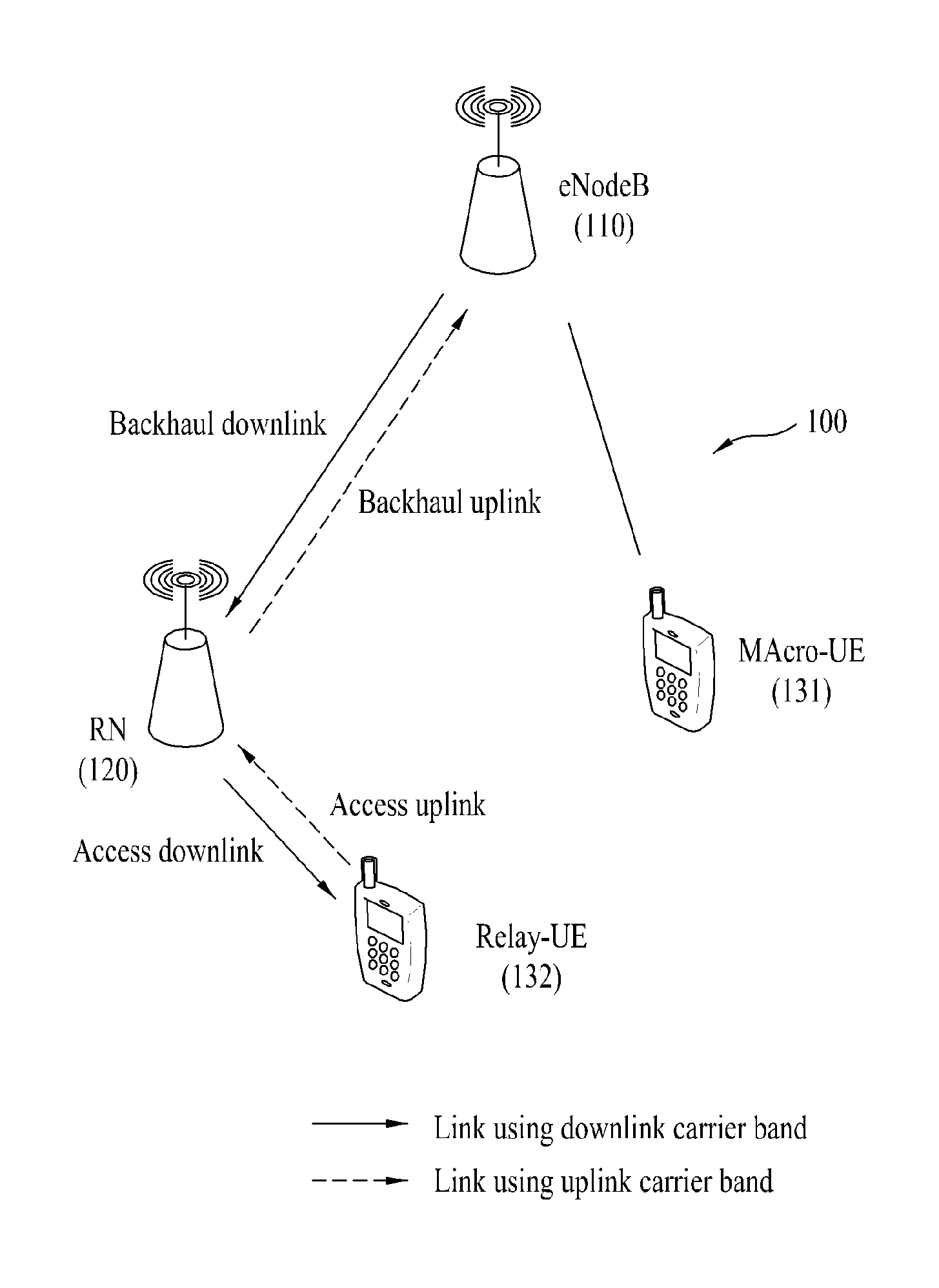
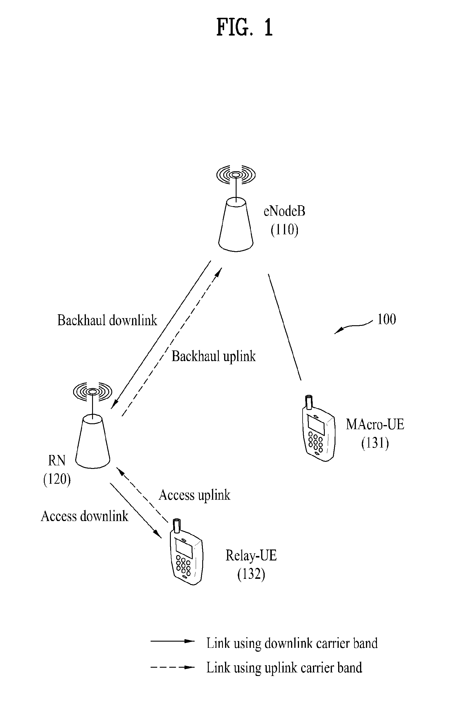
[0001]This application is a national stage application of PCT Application No. PCT / KR2010 / 003666, filed on Jun. 8, 2010, which claims the benefit of U.S. Provisional Application Nos. 61 / 185,188, filed Jun. 8, 2009, and 61 / 266,509, filed Dec. 4, 2009, all of which are hereby incorporated by reference.TECHNICAL FIELD[0002]The present invention relates to a wireless communication system and more particularly, to a method and apparatus for allocating carriers to a backhaul link and an access link at a relay in a multi-carrier wireless communication system.BACKGROUND ART[0003]FIG. 1 illustrates a Relay Node (RN) 120 and User Equipments (UEs) 131 and 132 within the coverage of an evolved Node B (eNode B or eNB) 110 in a wireless communication system 100. The RN 120 may transmit data received from the eNode B 110 to the UE 132 within its relay coverage and data received from the UE 132 to the eNode B 110. The RN may also extend a high-data rate area, increase the communication quality of a ...

Claims


Application Information

Patent Timeline
Patent Type & Authority Patents(United States)
IPC IPC(8): H04B7/14
CPCH04W72/0493H04L1/1854H04W84/047H04W72/0453H04L5/0007H04B7/2606H04L2001/0097H04B7/15542H04L5/0094H04L1/1861H04L1/1822H04L5/001H04J11/00H04W72/53
Inventor CHUNG, JAE HOONKWON, YEONG HYEONMOON, SUNG HOPARK, KYU JIN
Owner LG ELECTRONICS INC
Learn More