
Discontinuous linear motor system

a linear motor and continuous technology, applied in the direction of motor/generator/converter stopper, multiple dynamo-motor starters, dynamo-electric converter control, etc., can solve the problems of inability to achieve endless transport paths, difficult to increase traveling performance, and limited length of transport paths, so as to simplify the power supply system and reduce the cost

Active Publication Date: 2014-08-05
MURATA MASCH LTD
View PDF10 Cites 17 Cited by
  • Summary
  • Abstract
  • Description
  • Claims
  • Application Information

AI Technical Summary

Benefits of technology

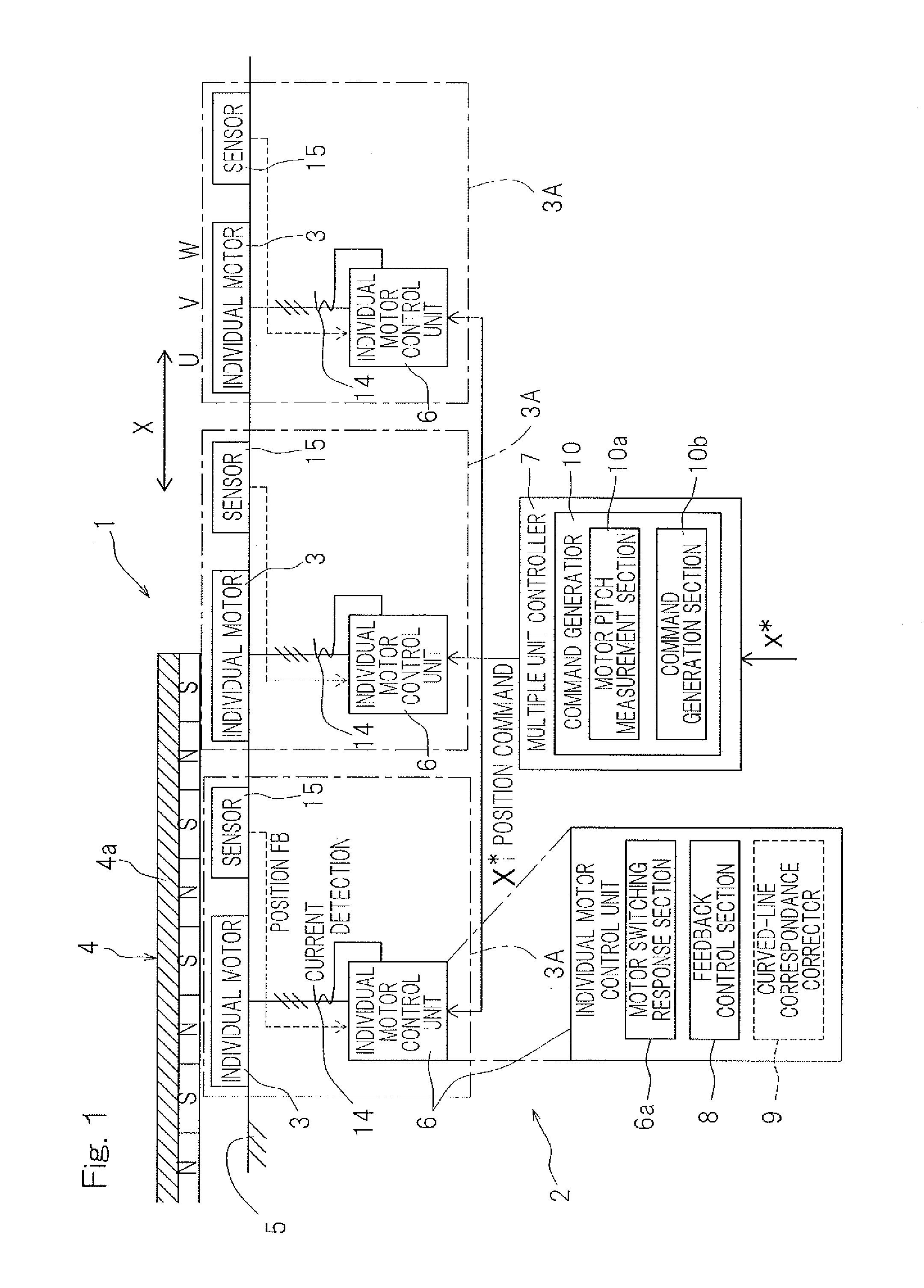
[0011]Preferred embodiments of the present invention enable a reduction in a number of coils to be used in a discontinuous linear motor system and a simplification of a power supply system by discontinuously disposing primary coils, and also enable components to be shared in plural portions of a path and cost to be reduced.
[0013]Since the individual motors which act as armatures on a primary side are discontinuously disposed as a stationary side, a reduction in a number of coils to be used can be accomplished, and also, a power supply system can be simplified as compared to a case where power is supplied to a movement side. Further, one of the plurality of individual motors that act as armatures on the primary side, the sensor, and the individual motor control unit to control the one of the plurality of individual motors are provided so as to define a set, and the individual motor, the sensor, and the individual motor control unit are disposed along the coil-aligned direction. Therefore, the components can be shared in plural portions of the path, and cost can be reduced.
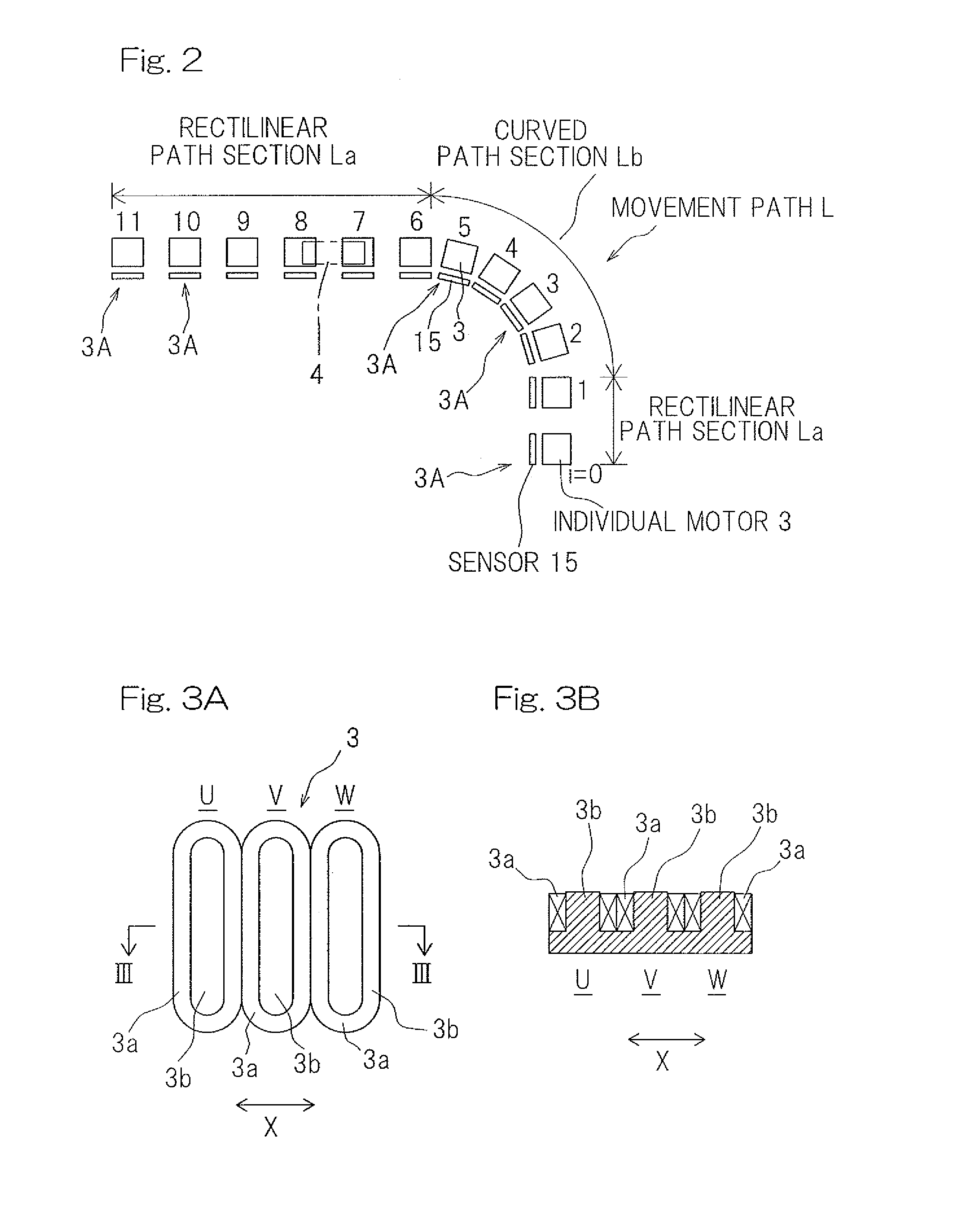
[0014]According to a preferred embodiment of the present invention, the movement path of the mover may include a curved path section, and each of the individual motor control units arranged to control the individual motors disposed in the curved path section may include a curved-line correspondence corrector arranged to correct a detection value obtained from the sensor according to a relationship between a curved line of the curved path section and a position of the sensor, so as to control the individual motors with the use of the corrected detection value. According to the above arrangement, the same components as provided in the rectilinear path section, as a set of the individual motor, the sensor, and the individual motor control unit, are used also in the curved path section, and the individual motor control unit is simply provided with the curved-line correspondence corrector configured by a program in the curved path section so as to enable position control and speed control to be accurately performed in the curved path section.
[0024]Thus, a magnetic pole position can be accurately detected in the curved path section, and accurate position control and speed control can be performed in the curved path section. In the synchronous type of linear motor, when an inrush of the mover including the permanent magnets into the individual motors occurs, a coil inductance and / or interlinkage magnetic flux vary according to a position. Therefore, current control based on the magnetic pole position is significant for accurate position control and speed control. For the current control based on the magnetic pole position, the accurate detection of the magnetic pole position is necessary. However, when the sensor acting as a linear scale is used, it is difficult to detect the magnetic pole position in the curved path section. This problem can be solved by the technique using the Equation 1 indicated above.
[0033]Thus, a position command for each individual motor is generated by using a magnetic pole position, a positional relationship between the sensor and the path, an offset value for a sensor output, and the like. Therefore, even the discontinuous linear motor can advantageously compensate a non-linearity of outputs from the sensors.

Problems solved by technology

The linear induction motor has a thrust so low that it is difficult to increase the traveling performance, and therefore, an attempt to employ a linear induction motor has been made in applying the conveyance system to the transport apparatus acting as the machine tool loader.
However, in order to move the coil side, a supply of electric power to the mover is required and, hence, in view of the necessity of wiring lines, it is impossible to accomplish an endless transport path and the transport path tends to be limited in length, and also, the power feeding system tends to become complicated.
However, in a case where the primary coils are disposed on the ground side, if the coils are continuously disposed over the entire length of a movement path, as is the case in the conventional linear motors, coils to be used are increased, which leads to increased costs.
However, a control method thereof and the use of sensors have not been specified.
Furthermore, a conventional standard linear motor needs to have a dedicated control device to perform a position control and a speed control in a curved path section, and the control device cannot double as a device for control of running on a rectilinear path section.
Therefore, there is a problem that a linear motor system including a curved path section causes an increase in cost.
Moreover, high-precision detection of magnet pole positions in the curved path section cannot be performed, so that positioning and speed control in the curved path section cannot be accurately performed.

Method used


Image

  • Discontinuous linear motor system
  • Discontinuous linear motor system
  • Discontinuous linear motor system

Examples


Embodiment Construction

[0053]Preferred embodiments of the present invention will be described with reference to FIG. 1 to FIG. 12. In FIG. 1, a discontinuous linear motor system of the present preferred embodiment preferably includes a linear motor 1 and a control device 2 that controls the linear motor 1. The linear motor 1 is preferably a linear synchronous motor (LSM), and preferably is a discontinuous linear motor which includes a movable magnet array or mover 4 and a plurality of individual motors 3 acting as armatures spaced from each other in a mover moving direction X. Each of the individual motors 3 functions as an armature on a primary side of one independent linear motor, and is provided on a common frame 5 including a rail (not shown) of the mover 4. In addition, a sensor 15 acting as a position detector that detects a position of the mover 4 is preferably provided on the frame 5 for each individual motor 3. Although each sensor 15 is illustrated as being positioned between the individual moto...


PUM


Abstract

A linear motor system includes a discontinuous linear motor and motor control device. The discontinuous linear motor includes a mover and a plurality of individual motors spaced from each other along a movement path of the mover. Each of the individual motors functions as an armature on a primary side of one independent linear motor. A sensor, arranged to act as a linear scale, is disposed for each individual motor and detects a position of the mover. The motor control device includes a plurality of individual motor control units and a multiple unit controller to comprehensively control the individual motor control units. The individual motor control units control the individual motors disposed in curved path sections, and each of the individual motor control units includes a curved-line correspondence corrector to correct a detection value obtained from the sensor according to a relationship between a curved line of the path and a position of the sensor.

Description

CROSS-REFERENCE TO THE RELATED APPLICATION[0001]The present application is a continuation application, under 35 U.S.C §111(a) of international application No. PCT / JP2011 / 072003, filed Sep. 27, 2011, which claims Convention priority to Japanese patent application No. 2010-239600, filed Oct. 26, 2010, the entire disclosure of which is herein incorporated by reference as a part of this application.BACKGROUND OF THE INVENTION[0002]1. Field of the Invention[0003]The present invention relates to discontinuous or discrete linear motor systems used to drive transport apparatuses for use in machine tools and industrial machinery, and for driving various other devices.[0004]2. Description of the Related Art[0005]Linear motors have been employed in, for example, a conveyor carriage employed in a physical distributing apparatus or a transport apparatus acting as a machine tool loader (for, example, JP Laid-open Patent Publication No. 63-114887). While the linear motor is available in various ty...

Claims


Application Information

Patent Timeline
Patent Type & Authority Patents(United States)
IPC IPC(8): H02P6/00H02P5/46H02P5/54H02P25/06
CPCH02P6/006H02K11/0015H02K16/04H02K41/031H02K2213/03H02K2213/12H02P25/06H02K11/21H02P25/064Y10S388/902H02P25/062
Inventor SATO, TOMOKI
Owner MURATA MASCH LTD
Learn More