Line illumination device and image input apparatus using the same

A lighting device and wiring technology, which is applied to the components of lighting devices, lighting devices, lighting and heating equipment, etc., and can solve the problems of unrecorded storage, unrecorded light guide and light source storage, etc.

Inactive Publication Date: 2008-10-01
MITSUBISHI ELECTRIC CORP
View PDF3 Cites 7 Cited by
  • Summary
  • Abstract
  • Description
  • Claims
  • Application Information

AI Technical Summary

Problems solved by technology

However, in Patent Document 2, it is described that the light guide is accommodated by a cover, but there is no description in any of the Patent Documents that not only the light guide but also the light source (light source unit or light source module) are also accommodated in the cover or the frame. Structure
That is, in the above-mentioned patent documents, there is no description of such a compact structure that accommodates the light guide and the light source in the frame.

Method used


Image

  • Line illumination device and image input apparatus using the same
  • Line illumination device and image input apparatus using the same
  • Line illumination device and image input apparatus using the same

Examples


Embodiment approach 1

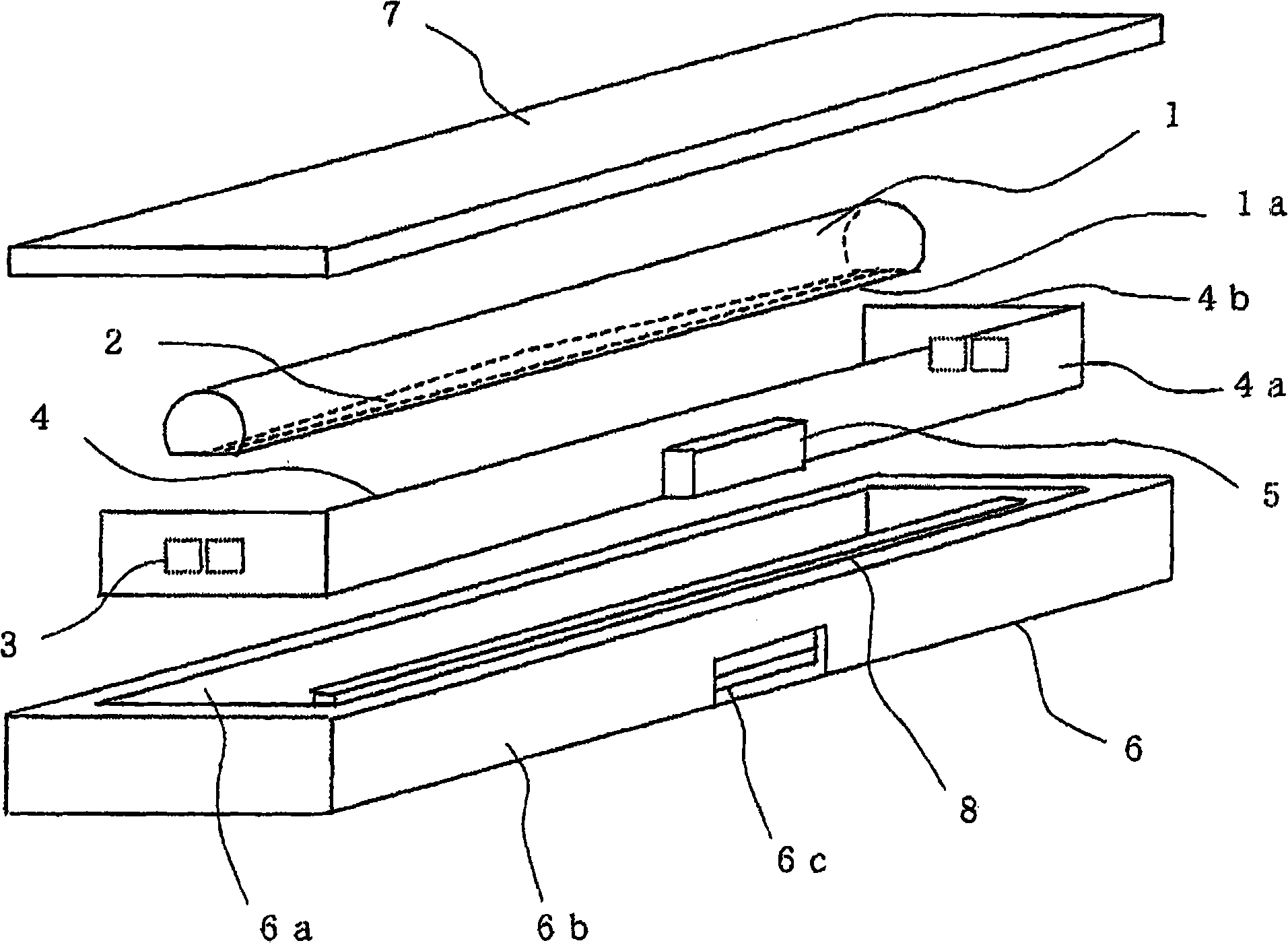
[0031] Now use Figure 1 and figure 2 Embodiment 1 will be described. FIG. 1 is a cross-sectional configuration diagram of a line lighting device according to Embodiment 1. FIG. in addition, figure 2 It is an exploded perspective view of the line lighting device shown in FIG. 1 . In Figure 1 and figure 2 In the figure, 1 is a light guide body, and the cylindrical lower part is cut|disconnected in the longitudinal direction, and the flat part 1a is formed. 2 is a light reflection layer formed by printing a white coating material on the flat portion 1 a of the light guide 1 . Furthermore, the cross-sectional shape of the light guide body 1 is not limited to those shown in FIG. 1 and figure 2 The illustrated semi-cylindrical shape may also be a polygonal shape, but the flat portion 1a forming the reflective layer 2 is its lower surface. 3 is a light source, for example, in addition to red (R) LED, green (G) LED, blue (B) LED, other infrared light sources can also be used as ...

Embodiment approach 2

[0039] Next, an image input device according to Embodiment 2 will be described with reference to FIG. 4 . FIG. 4 is a cross-sectional configuration diagram of an image input device according to Embodiment 2. FIG. In FIG. 4, 10 is the line lighting device of the structure already demonstrated in Embodiment 1. As shown in FIG. 11 is a light receiving device. A document is conveyed between the light receiving device 11 and the line illuminating device 10 . Note that the manuscript includes banknotes and the like. The light emitted from the line illuminating device 10 passes through the document and is collected by the lens body 12 of the light receiving device 11 . The light condensed by the lens body 12 is received by the sensor 14 arranged on the substrate 13 and undergoes photoelectric conversion. Furthermore, 15 is a glass plate. In this way, if the line illuminating device according to Embodiment 1 is used as a light source for a transmissive image sensor, since it is c...


PUM


Abstract

The invention provides a line illumination device with a compact structure containing a light source and a light-guiding body inside a frame as well as a simple power supply structure of the light source, and an image input device using the line illumination device. The rod-shaped light-guiding body (1) is contained inside the frame (6), and the light source (3) emitting light into the light-guiding body (1) is arranged at the end part of the light-guiding body (1) so that a flexible substrate (4) loading the light source (3) is bent and contained inside the frame (6); wiring installed on the flexible substrate (4) supplies power for the light source (3) so as to emit out line-shaped light from the light-guiding body (1).

Description

technical field [0001] The present invention relates to a line illuminating device that injects light from a light source into a light guide and emits it in a linear form, and an image input device using the line illuminating device for discriminating banknotes and the like. Background technique [0002] Conventionally, image sensors have been used in equipment such as facsimile machines and scanners. For the image sensor, a line illumination device is generally used. [0003] [Patent Document 1] Japanese Patent Laid-Open No. 2001-357429 (Fig. 3) [0004] [Patent Document 2] Japanese Patent Laid-Open No. 2003-60854 (Fig. 1) [0005] [Patent Document 3] Japanese Patent Laid-Open No. 2004-64146 (Fig. 1) [0006] As such a line lighting device, Patent Document 1 ( FIG. 3 ) describes a configuration in which LEDs mounted on a substrate are arranged on side surfaces (ends) of a light guide. In addition, Patent Document 2 ( FIG. 1 ) describes a structure in which a light guide...

Claims


Application Information

Patent Timeline
Patent Type & Authority Applications(China)
IPC IPC(8): H04N1/04F21V8/00F21V19/00F21V23/00
CPCG02B6/0001G07D7/121H04N1/02815H04N1/02835H04N2201/02462H04N2201/02485
Inventor 伊藤笃有本浩延荒牧彻
Owner MITSUBISHI ELECTRIC CORP
Why Eureka
Try Eureka