Eureka AIR delivers breakthrough ideas for toughest innovation challenges, trusted by R&D personnel around the world.

Power supply apparatus and crane system

A technology of power supply device and crane, which is applied to cranes, trolley cranes, transportation and packaging, etc., can solve problems such as no records, and achieve the effect of reducing possibility and easy power supply

Inactive Publication Date: 2011-07-20
MITSUBISHI HEAVY IND LTD
View PDF4 Cites 8 Cited by
  • Summary
  • Abstract
  • Description
  • Claims
  • Application Information

AI Technical Summary

Problems solved by technology

[0004] However, in the self-propelled crane power supply device described in (Japanese) Unexamined Patent Publication No. 2009-242101, it is not described that the rail for power supply is installed at a place higher than the height of the operator, and the operator may come into contact with it. track

Method used


Image

  • Power supply apparatus and crane system
  • Power supply apparatus and crane system
  • Power supply apparatus and crane system

Examples


Embodiment Construction

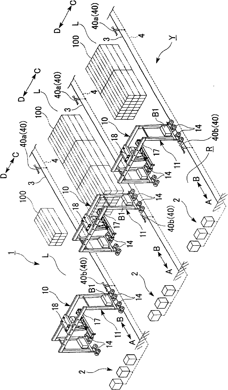
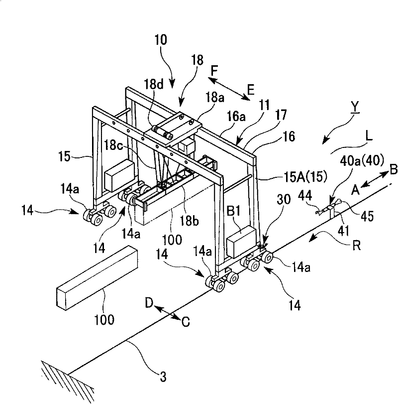
[0042] The power supply device 30 , the self-propelled crane 10 equipped with the power supply device 30 , and the crane system 1 including a plurality of self-propelled cranes according to an embodiment of the present invention will be described below.

[0043] figure 1 It is an overall view showing a crane system 1 including a plurality of self-propelled cranes 10 . Such as figure 1 As shown, the crane system 1 of this embodiment includes: a plurality of walking passages L arranged on the road surface R in the container yard Y; a plurality of self-propelled cranes 10 traveling in each walking passage L; a plurality of external power sources 2 . The external power supply 2 is provided as an external device corresponding to each traveling passage L, and supplies electric power to each traveling crane 10 .

[0044] In the crane system 1 of the present embodiment, the ground guide line 3 is provided on the road surface R along the extending direction A-B of each running passa...


PUM


Abstract

The invention provides a power supply apparatus and a crane system. The power supply apparatus is provided with: at least one power collector which supplies electric power to a rechargeable battery equipped on a self-traveling crane; and a position adjusting section which is provided between a crane main body of the self-traveling crane and the power collector, and which adjusts a position in a widthwise direction orthogonal to a traveling direction of the self-traveling crane, of the power collector with respect to the self-traveling crane. The power collector comes in contact, through an opening formed in an insulation cover which covers the power supply section, with a power supply section which is provided on a side section on a traveling pathway of the self-traveling crane, and supplies electric power to the self-traveling crane. The opening is formed in a region including a bottom section of the insulation cover facing a pathway surface where the self-traveling crane travels, and opposite end sections of the insulation cover in the traveling direction of the self-traveling crane.

Description

technical field [0001] The invention relates to a power supply device and a crane system. Background technique [0002] Conventionally, self-propelled cranes that travel along passages of container yards have been known as cranes for transporting containers stored in container yards or the like. [0003] As an example of such a self-propelled crane, in (Japanese) Unexamined Patent Publication No. 2009-242101, a self-propelled crane (site crane) that includes a power supply device and a rechargeable battery and travels using the power stored in the rechargeable battery is described. . In the self-propelled crane described in (Japanese) Unexamined Patent Publication No. 2009-242101, a rail for power supply formed along the length direction of the passage is provided near the passage for storing containers, and the self-propelled crane is provided in contact with the rail in a telescopic or rotational manner. device for receiving electricity. According to the self-propelled ...

Claims


Application Information

Patent Timeline
Patent Type & Authority Applications(China)
IPC IPC(8): B66C13/12B66C25/00
CPCB66C19/007B66C13/12
Inventor 吉冈伸郎
Owner MITSUBISHI HEAVY IND LTD
Why Eureka
Eureka Blog
Learn More