
NP-EIFS non-permissive exterior insulation and finish systems concept technology and details

a technology of exterior wall covering and non-permissive, applied in the direction of heat insulation, snow traps, building repairs, etc., can solve the problems of water accumulation serious and vexing problems associated with eifs construction, and enter behind the exterior wall covering

Active Publication Date: 2014-07-29
RADOANE MARIUS
View PDF17 Cites 22 Cited by
  • Summary
  • Abstract
  • Description
  • Claims
  • Application Information

AI Technical Summary

Benefits of technology

The invention provides a system for installing a thermal barrier on a building's surface that prevents air and vapor leakage inside the insulation, while also preventing the formation of wind driven rain and snow. This system reduces installation time and cost, while minimizing the space needed for air within the insulation. Additionally, the invention includes a process for installing a non-permissive exterior insulation and finish system, as well as a sealant ensemble system for perimeter seal, which can withstand the effects of water vapor transmission and absolute humidity differential, and prevent the formation of dew points within the insulation cladding.

Problems solved by technology

While such EIFS have proved to be quite satisfactory for ease of installation, insulating properties, and ability to receive a variety of aesthetically pleasing finishes, a serious and vexing problem associated with EIFS construction exists.
This problem is one of water accumulation behind the exterior wall covering.
Wind-driven water that may enter behind the exterior wall covering may be the result of poor workmanship or design, deterioration of flashing or sealants over time, lesser quality doors and windows, or any other penetration or compromise of the exterior finish.
Drainable systems have difficulties when it needs to drain water among windows, and when vertical walls end with ceiling or beam.
Soffits have no solutions to drain condensation water.
In addition, the moist environment is a breeding ground for wood consuming insects and health hazards such as various varieties of molds.
These attempts have not been completely successful.
Sealants are not only difficult to properly install, but tend to deteriorate and separate from the wall components due to climatic conditions, building movement, the surface type, or chemical reactions.
Flashing is also difficult to install and may tend to hold the moisture against the wall component.
These materials are of no value in addressing the problem of moisture that has already entered a building wall cavity or moisture that penetrate the permeable EPS board and condensate on the moisture barrier surface.
The superior energy efficiency and design flexibility of EIFS have resulted in growing popularity, but the presence of moisture remains a vexing problem.
Practically, any material with high conductibility or air leakage from outside can cause condensation.
In hot-humid climates and seasons, moisture from the exterior flows towards the cooled interior by passing through the building enclosure, condensation occurs because interior surfaces are typically cold and subsequently accessed by moisture levels, which are too high.
The wall assembly is not properly protected from inside heat loss (cold loss), because the wall assembly materials are thermal conductive, metal or wood studs become thermal bridges, and fiberglass insulation from inside of the wall cavity is too permissive to air pressure differential between cold and hot.

Method used


Image

  • NP-EIFS non-permissive exterior insulation and finish systems concept technology and details
  • NP-EIFS non-permissive exterior insulation and finish systems concept technology and details
  • NP-EIFS non-permissive exterior insulation and finish systems concept technology and details

Examples


Embodiment Construction

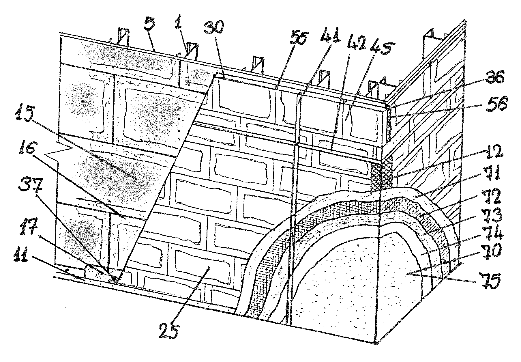
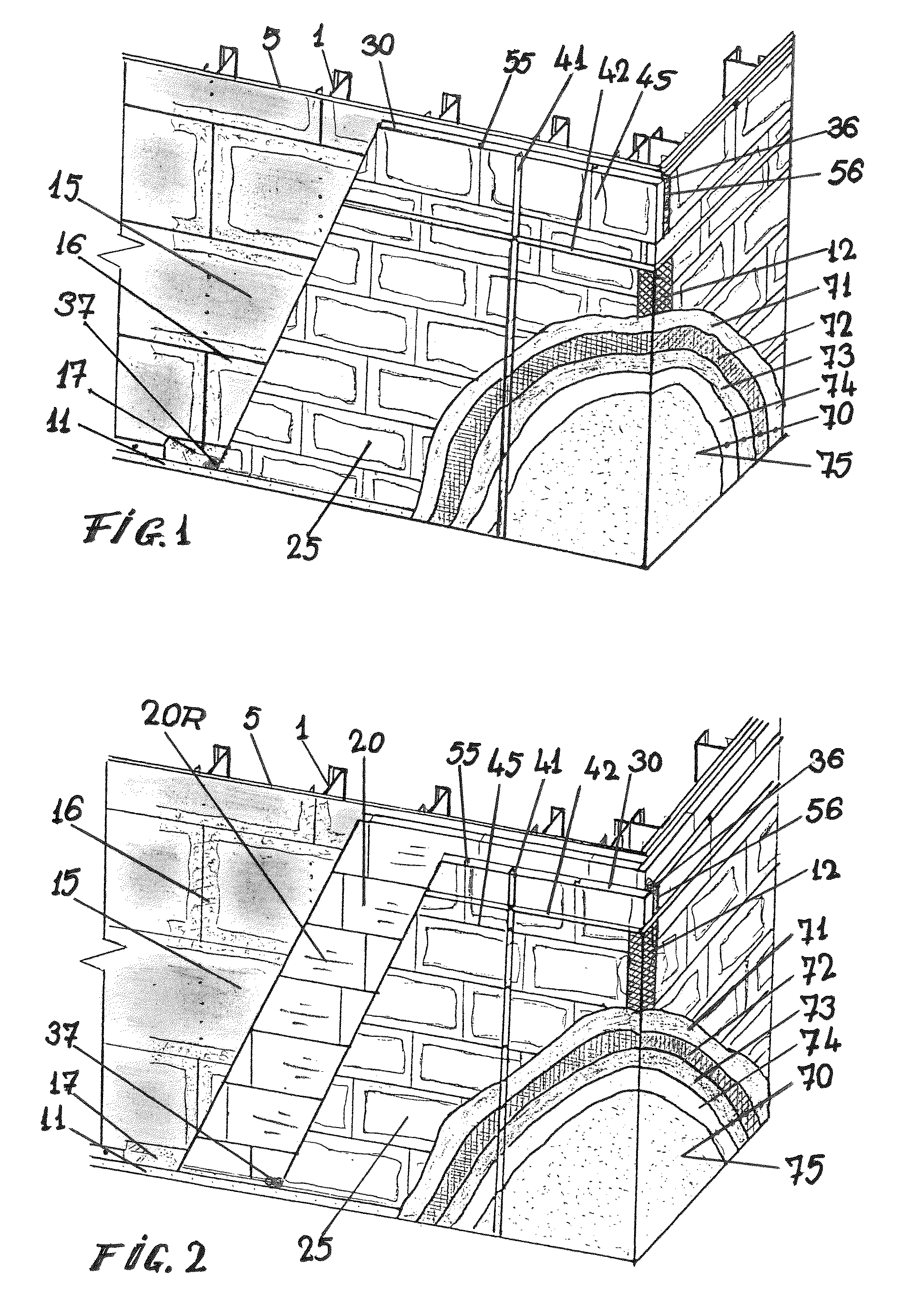
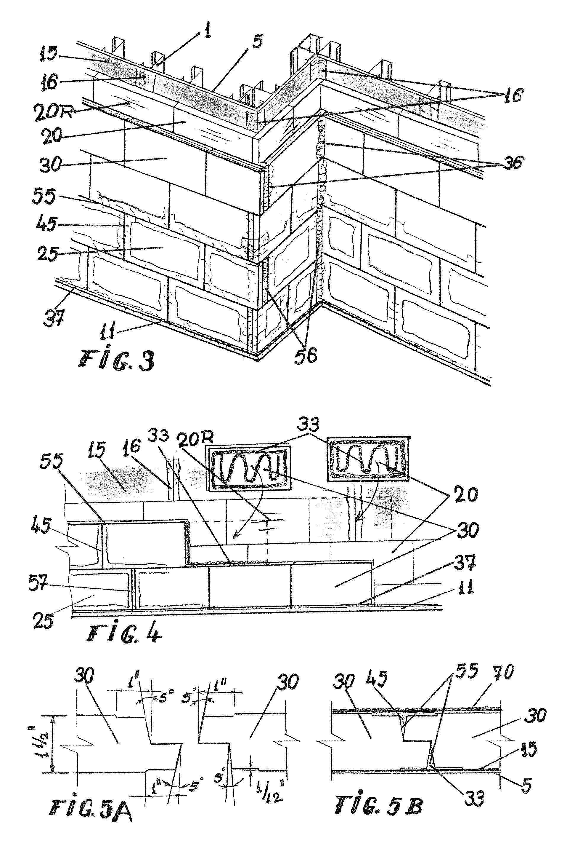
[0075]The present invention provides an impermeable to water and non-permissive to vapors exterior insulation and finish system, generically called NP-EIFS. Unlike exterior insulation and finish systems known in the prior art, the EIFS of the present invention provides a double layer of water and moisture protection, one applied to the substrate 5, a liquid membrane 15, to be moisture barrier for inside vapors, and an exterior weather and vapor barrier 25, which is created with extruded polystyrene, closed cell foam, insulation boards (XPS) 30, special assembled 55 (FIGS. 5A-5B) and sealed 45, to create a non-permissive insulation envelope of the enclosure.

[0076]To ensure the success of this new system and concept, it is necessary to analyze the materials involved to create these systems, according to the invention.

[0077]The substrate shall be engineered to withstand applicable design loads and wind loads, and free of foreign materials such as oil, dust, dirt, form release agents, p...


PUM

PropertyMeasurementUnit
RHaaaaaaaaaa
Temperatureaaaaaaaaaa

Abstract

A new concept wall system is provided, wherein the Exterior Insulation and Finish System cladding is created using components with no water absorption, a very low vapor permeability and sealing properties, accommodated with an installation technology which extend the materials properties to the assembly, together with bonding and sealing the intersections and terminations, creating a Non-Permissive to water and vapor diffusion, Exterior Insulation and Finish System (NP-EIFS). The present invention relates to an EIFS cladding having two air and vapor barriers, one applied to the substrate, a continuous liquid membrane with sheathing joints sealed to be moisture barrier for inside vapors, and an exterior weather and vapor barrier which is created using closed cell extruded polystyrene insulation boards, special assembled with joints sealed, to create a non-permissive insulation envelope of the enclosure. Another object of the invention is to provide waterproof and air / vapor-proof details, a new concept of flashing and sealant application around windows / doors and other constructive elements to avoid thermal bridges and air leakage inside thermal envelope and wall assembly. Methods of installation are included.

Description

FIELD OF THE INVENTION[0001]This invention relates to a new concept of the permissive exterior insulation and finish systems, to transform these systems into a non-permissive to water, air and vapor, exterior insulation and finish system.BACKGROUND OF THE INVENTION[0002]Exterior Insulation and Finish Systems (EIFS) are well known in the art. Such systems typically consist of a layer of substrate such as plywood, oriented-strand board OSB, gypsum sheathing etc, an insulation layer such expanded polystyrene, mesh embedded in a coat of polymer modified cement and polymeric finish. Originally, EIFS was an exterior wall concept designed to have high insulation values and a reliable stucco finish that could be economically created in a wide array of textures and colors. Generally, these systems include an exterior wall having an expanded polystyrene foam insulation board EPS, attached via an adhesive or mechanical fasteners to the substrate. The exterior of the insulation, after all detai...

Claims


Application Information

Patent Timeline
Patent Type & Authority Patents(United States)
IPC IPC(8): E04C1/00
CPCE04B2/88E04B1/70E04C2/243E04C2/44H02G3/36E04B2/58E04B1/665E04C2/205E04F13/04E04B1/6803E04B1/7625E04B1/7641E04B1/80
Inventor RADOANE, MARIUS
Owner RADOANE MARIUS
Learn More