Device for compressing of empty deformable containers

Active Publication Date: 2014-07-22
SCHWELLING HERMANN
View PDF8 Cites 1 Cited by
  • Summary
  • Abstract
  • Description
  • Claims
  • Application Information

AI Technical Summary

Benefits of technology

This patent describes a machine that cuts and cracks paper. It has two working regions with larger outer diameters, and a groove is made in the surface of these regions to make it easier to grip the paper. The machine has rotating rollers that rotate at a speed of 60 rotations per minute. A stripper is also used to prevent gripping of the paper too tightly around the rollers. The starting pulse for the rollers is performed through a light barrier, and a lagging time is provided. These technical improvements make it easier to cut and crack paper using the machine.

Problems solved by technology

This arrangement is in particular expensive and service intensive because of the last recited device groups.
A further disadvantage is present were the distance of the pairwise arranged rollers, in particular those with the smallest distance of the axes, is not precisely adjusted with respect to the distance of the axes and the position of the there longitudinally directed blades.
In addition such smaller and smallest pieces are not always looked for in the further processing and frequently the further processing requires a plate shaped material.
If thus compressed plastic containers as well as compressed metal cans in a high quality are to be present for further processing or, respectively, a high throughput is to be achieved in the apparatuses with respect to each of the two types of starting material, then in most cases a separate apparatus is required for each type of empty containers, with which apparatus in fact also the other type of empty containers can be compressed, but not in an optimal way.
This fact entails among other things also a higher investment expenditure for the operator of such apparatuses.

Method used


Image

  • Device for compressing of empty deformable containers
  • Device for compressing of empty deformable containers
  • Device for compressing of empty deformable containers

Examples


Embodiment Construction

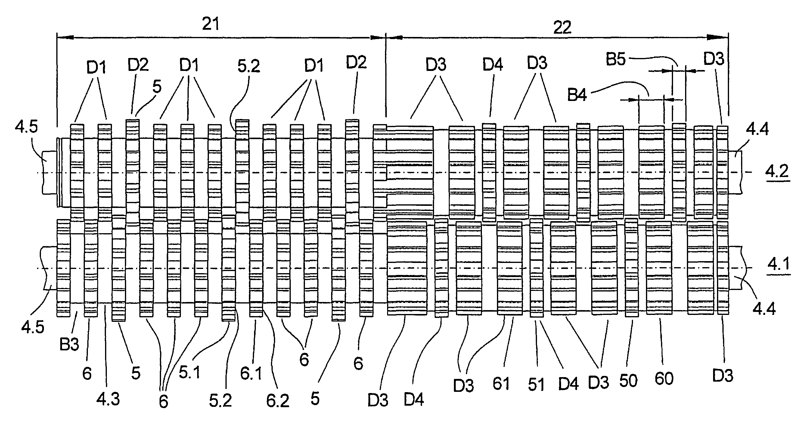
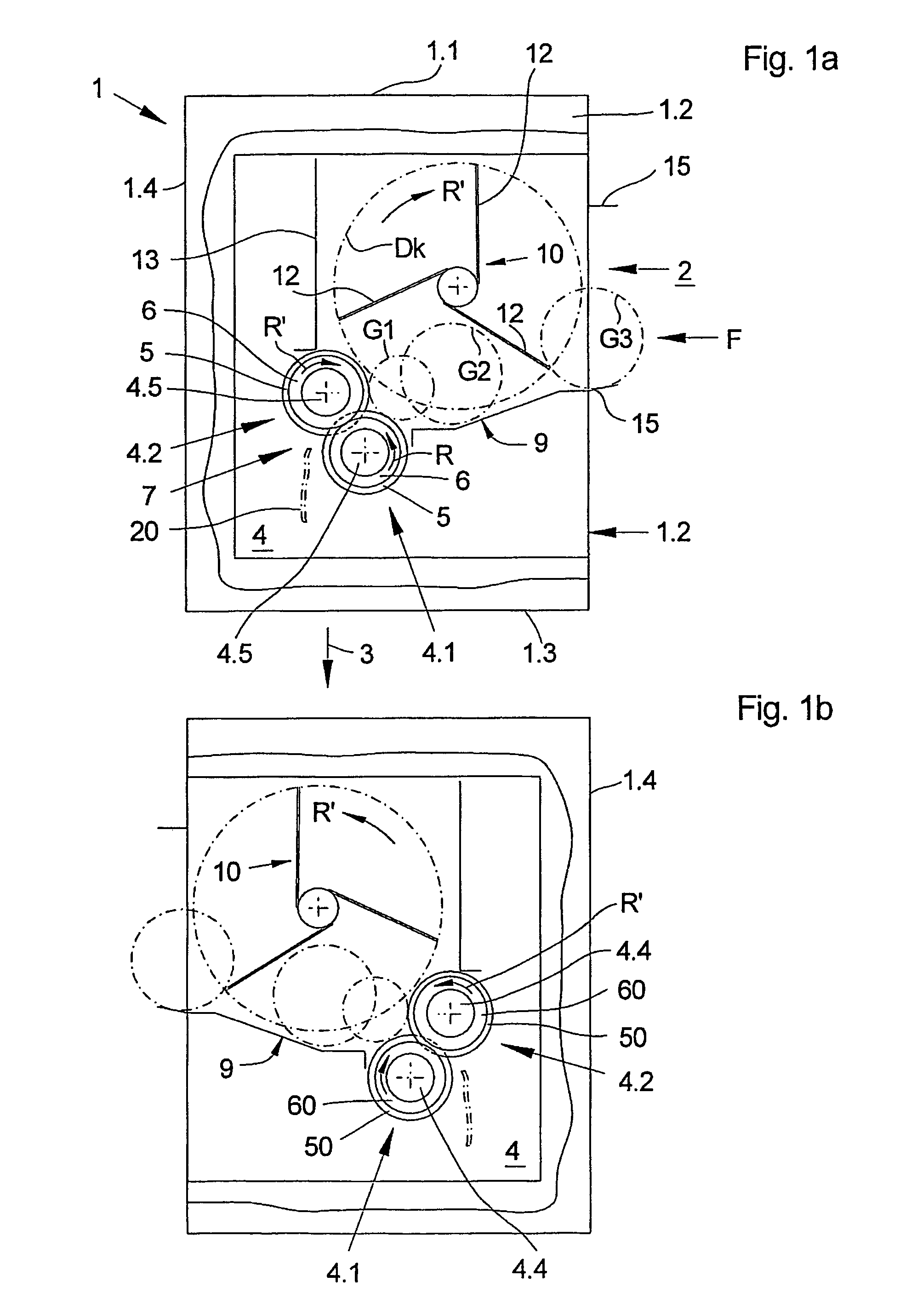
[0048]The new apparatus for compressing of empty containers is shown in the figures 1a and 1b in each case in a lateral view and with partially opened side face and the view onto the cutting unit and pressing unit 4 shown schematically. The apparatus comprises here a housing 1, with a filling opening 2 in the front side 1.2 of the housing 1 as well as an output opening 3, also called outlet opening, in the lower side 3.1 of the housing 1 and a cutting unit and pressing unit 4 disposed in the housing 1 as well as means, here not shown, for driving and for controlling the cutting unit and pressing unit 4. The upper side 1.1 and the rear side 1.4 of the housing 1 are closed according to the embodiment example.

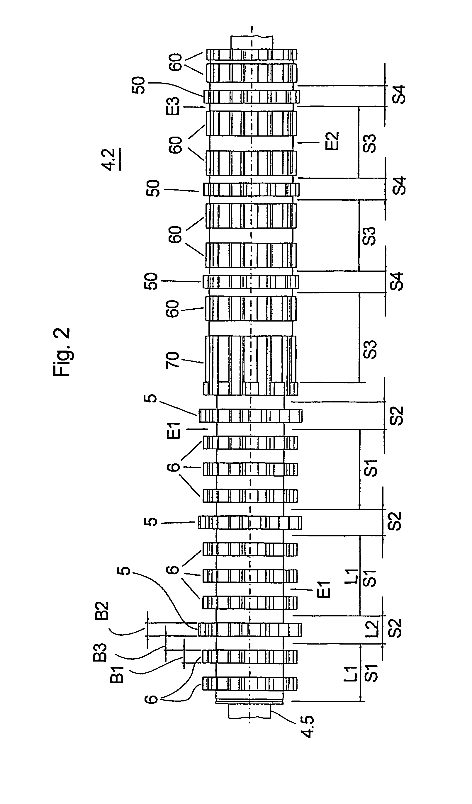
[0049]The cutting and pressing unit 4 comprises two rollers 4.1 and 4.2 disposed at a distance relative to each other and relative to their rotation axes A1, A2, compare FIG. 3b.

[0050]A sliding chute 9 is furnished from the lower edge of the filling opening to towards the cutting...


PUM


Abstract

An apparatus for compressing empty containers, in particular of beverage bottles or beverage cans made out of plastic, in particular out of polyethylene terephthalate PET, or tin plate. The apparatus has a cutting and pressing unit as well as means for driving and for controlling the cutting and pressing unit, wherein the cutting and pressing unit contains at least two cooperating, oppositely rotating rollers disposed at a distance relative to each other with respect to their rotation axes, wherein each roller has several disks in each case disposed towards each other with an axial distance (free space). According to a special further development it is proposed that at least in the operating region of the two rollers there are disposed axially next to each other a first working region for a compressing of containers made out of plastic and a second working region for a compressing of containers made out of metal.

Description

CROSS-REFERENCE TO RELATED APPLICATIONS[0001](not applicable)STATEMENT REGARDING FEDERALLY SPONSORED RESEARCH OR DEVELOPMENT[0002](not applicable)THE NAMES OF THE PARTIES TO A JOINT RESEARCH AGREEMENT[0003](not applicable)INCORPORATION-BY-REFERENCE OF MATERIAL SUBMITTED ON A COMPACT DISC[0004](not applicable)BACKGROUND OF THE INVENTION[0005](1) Field of the Invention[0006]The invention relates to a device for compressing empty containers, such as beverage bottles or beverage cans and similar waste materials.[0007](2) Description of Related Art including information disclosed under 37 CFR 1.97 and 1.98[0008]Such devices are employed for compacting empty containers, in particular containers out of the food region, such as beverage bottles, cans and the like deformable containers, for transport to the recycling plants or, respectively, for the recycling process itself.[0009]On the one hand, devices operating according to the principle of the plate pressing and on the other hand, such d...

Claims


Application Information

Patent Timeline
IPC IPC(8): B02C4/08B30B3/00B30B9/32
CPCB02C19/0081B30B9/325B02C18/142B30B9/301
Inventor SCHWELLING, HERMANN
Owner SCHWELLING HERMANN
Why Eureka
Try Eureka