
Prediction-based distributed parallel simulation method

a distributed parallel and simulation method technology, applied in the field of prediction-based distributed parallel simulation method, can solve the problems of low performance, extremely slow simulation speed, and difficult debugging, and achieve the effects of reducing the total verification time, high execution speed, and increasing verification efficiency

Inactive Publication Date: 2014-07-15
YANG SEI YANG
View PDF33 Cites 13 Cited by
  • Summary
  • Abstract
  • Description
  • Claims
  • Application Information

AI Technical Summary

Benefits of technology

This approach significantly reduces verification time, increases efficiency, and provides high visibility and controllability throughout the verification process from simulation-based to physical prototype-based verification, ensuring systematic and consistent debugging of design errors across abstraction levels.

Problems solved by technology

But, its shortcoming is a low performance comes from the fact that the simulation execution is a sequential execution of machine instructions sequence.
If the design complexity is large alike to the modern designs having 100 million or more gates, the simulation speed becomes extremely slow (for example, it will take 3.2 years to simulation an 100 million gates design for 100,000,000 cycles by an event-driven simulation whose speed is 1 cycle / sec).
However, as in the prototyping environment the visibility and controllability are very low, the debugging is very difficult when it operates incorrectly.
The design size of digital circuits or digital systems are growing to tens of million or hundreds of million gates and their functionality is becoming very complex as the IC (Integrated Circuit) design and fabrication technology has been being developed rapidly.
In the design process using progressive refinement the simulation at high level of abstraction can be run fast, but the simulation at low level of abstraction is relatively slow.
However, the performance of traditional distributed parallel simulation severely suffer from the communication and synchronization overhead among local simulators.
But, because current distributed parallel simulation using optimistic synchronization does not consider to minimize the roll-back by maximizing the simulation periods when a local simulation does not require any synchronization with other local simulations, the simulation performance degrades significantly due to the excessive roll-backs.
In summary, the synchronization and communication methods for both optimistic approach and pessimistic approach greatly limit the performance of distributed parallel simulation using two or more simulators.
However, in the current progressive refinement process there is no efficient method to maintain the model consistency between two models existing at two different abstraction levels.
Moreover, as there is no systematic method in the debugging process in which the design errors are identified and removed in the design process using the progressive refinement, the large amount of time must be consumed.

Method used


Image

  • Prediction-based distributed parallel simulation method
  • Prediction-based distributed parallel simulation method
  • Prediction-based distributed parallel simulation method

Examples


Embodiment Construction

[0219]The accompanying drawings, which are included to provide a further understanding of the invention and which constitute a part of the specification, illustrate embodiments of the invention and together with the description serve to explain the principles of the invention.

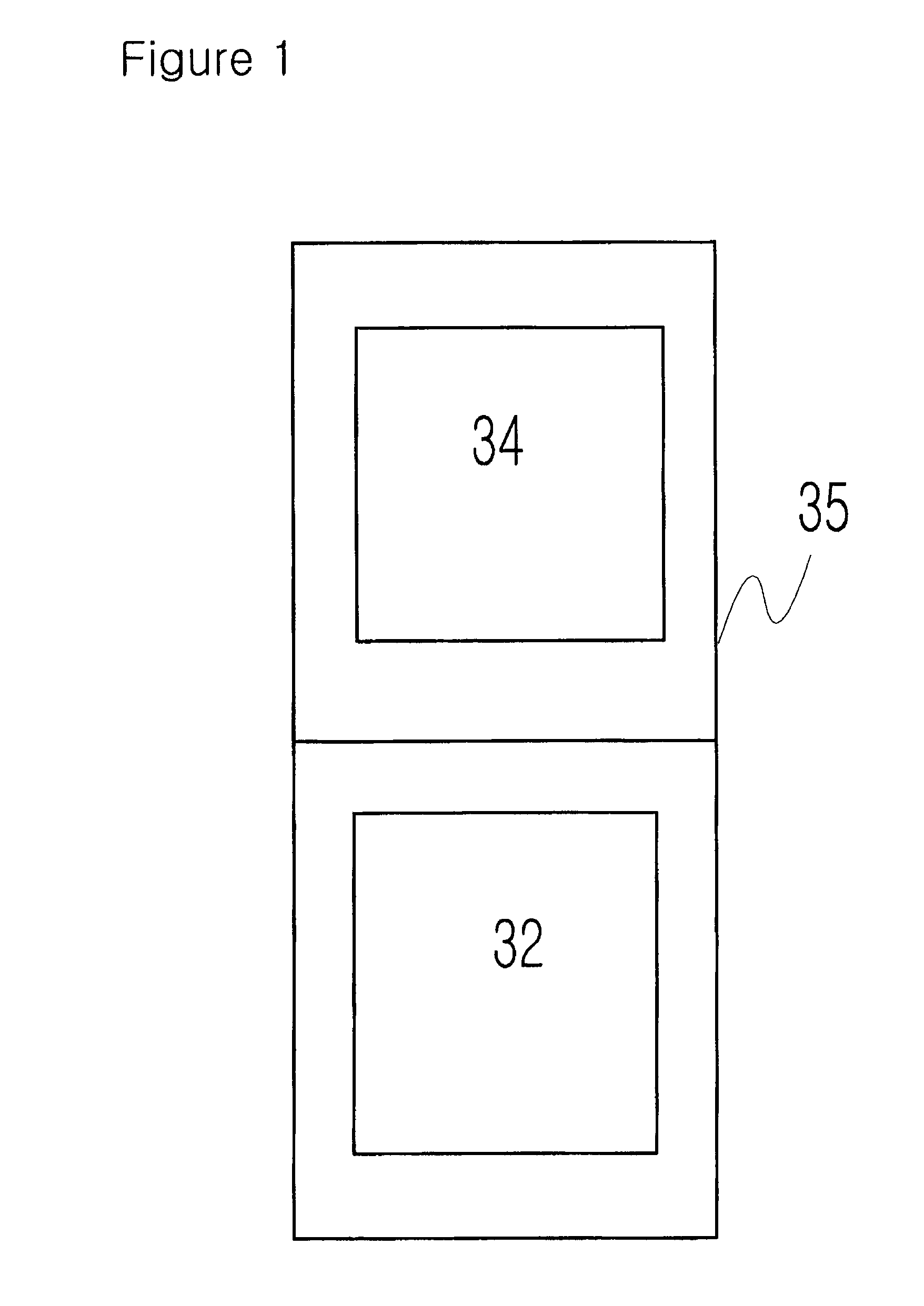
[0220]FIG. 1 is a schematic diagram of an example of the design verification apparatus in this present invention.

[0221]In FIG. 1, reference numeral 32 denotes verification software, reference numeral 34 denotes HDL simulator, and reference numeral 35 denotes computer.

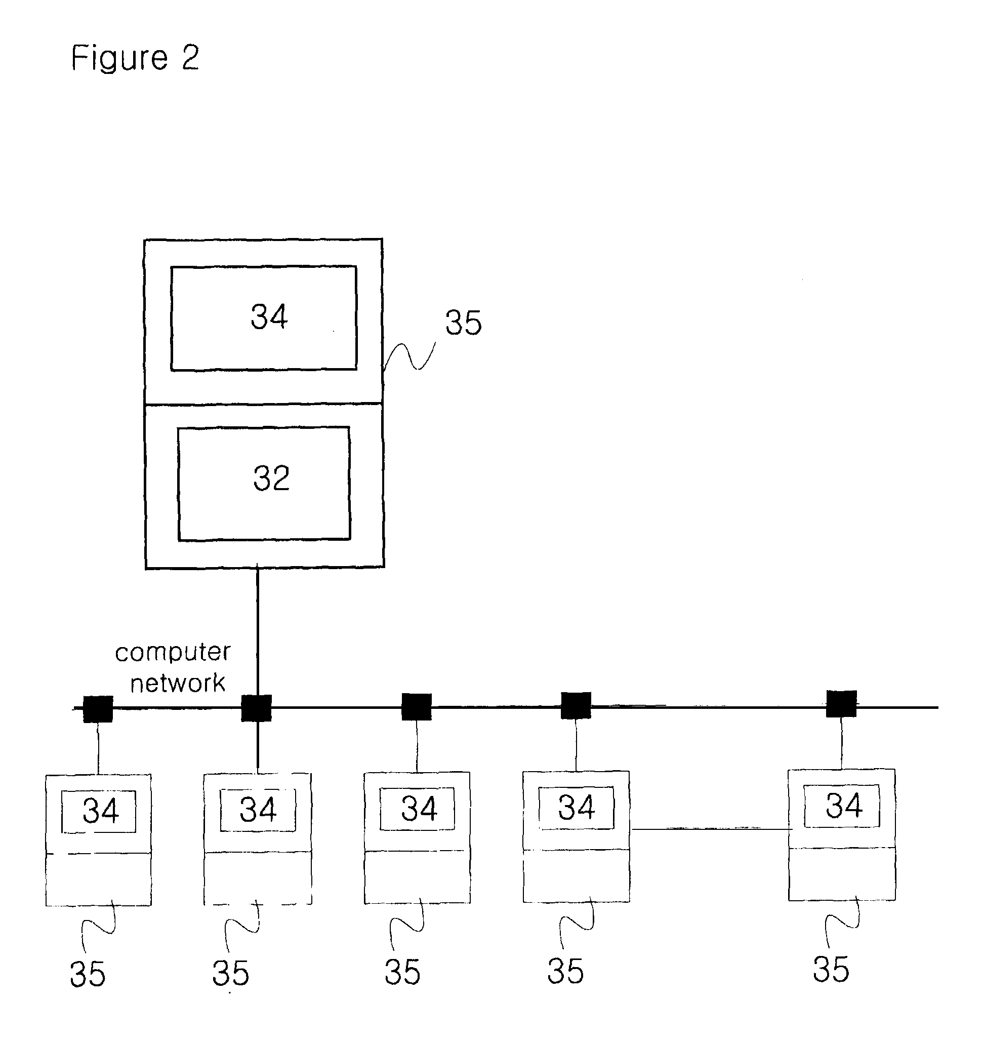
[0222]FIG. 2 is another schematic diagram of an example of the design verification apparatus in this present invention.

[0223]In FIG. 2, a plurality of computers 35 are connected to computer network.

[0224]FIG. 3 is a schematic diagram of an example of the hierarchy of an ESL model and its corresponding hierarchy of a RTL model.

[0225]The design verification apparatus that can be used for applying the design verification method in the present inventio...


PUM


Abstract

The simulation consists of a front-end simulation and a back-end simulation. The front-end simulation can use an equivalent model at different abstraction level, or a simulation model for the back-end simulation. The back-end simulation uses the simulation result of front-end simulation so that it can run one or more simulation runs sequentially or in parallel. Alternatively, models at lower level of abstraction are simulated together with a model at higher level of abstraction in parallel using two or more simulators.

Description

CROSS-REFERENCE TO RELATED PATENT APPLICATIONS[0001]This application is a continuation-in-part of application Ser. No. 12 / 089,665, filed Apr. 9, 2008, which is National Phase entry case of PCT Application PCT / KR2006 / 004059 filed on Oct. 10, 2006.[0002]Also, this application claims the benefit of Korean Patent Application No. 10-2005-0095803, Korean Patent Application No. 10-2005-0098941, Korean Patent Application No. 10-2005-0122926, Korean Patent Application No. 10-2005-0126636, Korean Patent Application No. 10-2006-0006079, Korean Patent Application No. 10-2006-0019738, Korean Patent Application No. 10-2006-0037412, Korean Patent Application No. 10-2006-0038426, Korean Patent Application No. 10-2006-0043611, Korean Patent Application No. 10-2006-0048394, Korean Patent Application No. 10-2006-0068811, Korean Patent Application No. 10-2006-0092573, and Korean Patent Application No. 10-2006-0092574, filed in Korean Intellectual Property Office, the disclosure of which is incorporated...

Claims


Application Information

Patent Timeline
Patent Type & Authority Patents(United States)
IPC IPC(8): G06F7/62G06F17/50
CPCG06F17/5022G06F30/33
Inventor YANG, SEI, YANG
Owner YANG SEI YANG
Learn More