
Electric power steering system

a technology of electric power steering and steering wheel, which is applied in the direction of steering initiation, special purpose vessels, instruments, etc., can solve the problems of more obvious noise and vibration, and achieve the effect of increasing quietness and good steering feel

Inactive Publication Date: 2014-07-15
JTEKT CORP
View PDF21 Cites 7 Cited by
  • Summary
  • Abstract
  • Description
  • Claims
  • Application Information

AI Technical Summary

Benefits of technology

[0013]It is an object of the invention to provide an electric power steering system with which quietness is increased while a good steering feel is maintained.

Problems solved by technology

One of the major factors of noise and vibration that are generated due to an operation of the motor used as the drive source is a ripple component contained in the detected steering torque.
Therefore, the noise and vibration tend to become more obvious when the absolute value of the assist gradient is large.

Method used


Image

  • Electric power steering system
  • Electric power steering system
  • Electric power steering system

Examples


first embodiment

[0028]Hereafter, the invention will be described with reference to the accompanying drawings.

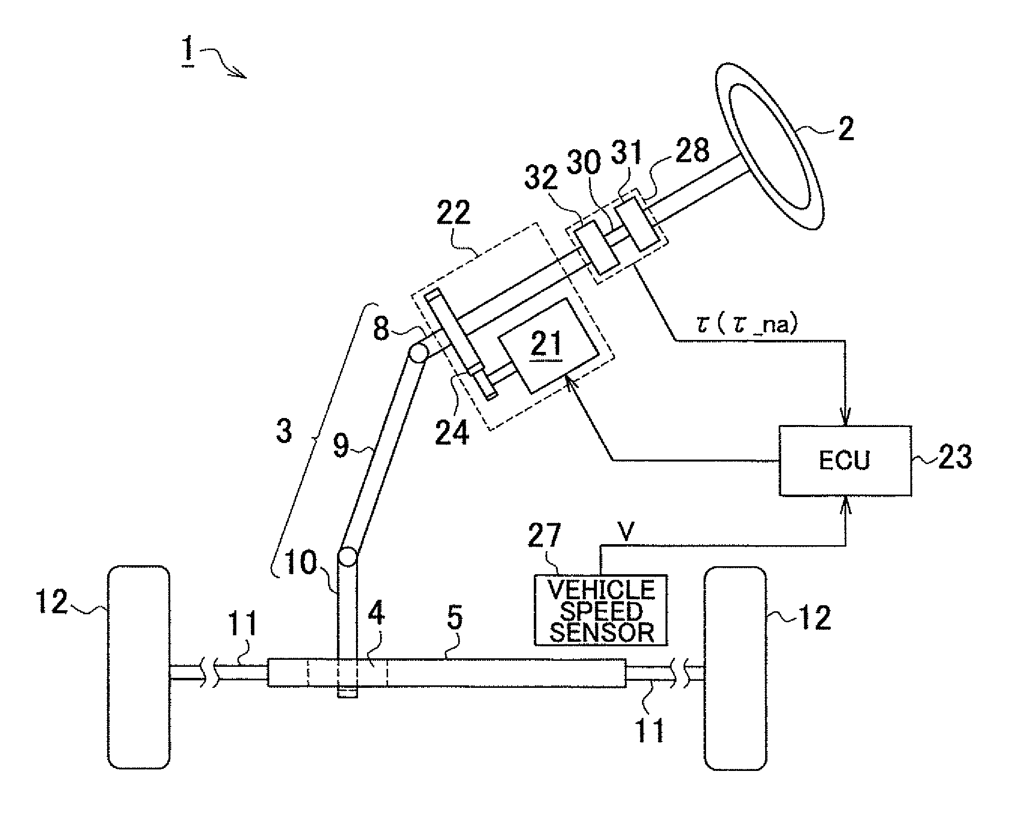
[0029]As shown in FIG. 1, in an electric power steering system (EPS) 1 according to the first embodiment, a steering shaft 3 to which a steering wheel 2 is fixed, is connected to a rack shaft 5 via rack-and-pinion mechanism 4. The rotation of the steering shaft 3 caused by a steering operation is converted into a linear reciprocation of the rack shaft 5 by the rack-and-pinion mechanism 4. The steering shaft 3 is formed by connecting a column shaft 8, an intermediate shaft 9, and a pinion shaft 10 to each other. The linear reciprocation of the rack shaft 5 caused by the rotation of the steering shaft 3 is transmitted to knuckles (not shown) via tie-rods 11 connected to respective ends of the rack shaft 5. As a result, the steering angle of steered wheels 12, that is, the direction in which a vehicle travels is changed.

[0030]The EPS 1 includes an EPS actuator 22 and an ECU 23. The EPS actuator...

second embodiment

[0073]In the second embodiment described above, the steering speed ω is calculated based on the steering angle detected by an existing steering sensor (not shown). However, the manner for calculating the steering speed ω is not limited to this. For example, if there are wheel speed sensors that detect the wheel speed of a right wheel and the wheel speed of a left wheel, the steering speed ω may be calculated based on the steering angle obtained from the difference in wheel speed between the right wheel and the left wheel. When it is possible to detect the rotational angle of the motor, for example, when a brushless motor is used as the motor 21 that serves as the drive source, the steering speed ω may be detected based on the rotational angle of the motor. In this case, the steering speed ω is used as a basis for determining whether resonance of the vibration due to the operation of the motor 21 occurs as described above. Accordingly, the feedback gains may be changed based on the r...


PUM


Abstract

A motor control signal output unit of an electric power steering system includes a feedback gain calculation unit (52), and a feedback control unit executes a feedback control with the use of a proportional gain (Kp) and an integral gain (Ki) that are calculated by the feedback gain calculation unit (52). The feedback gain calculation unit (52) sets the feedback gains to large values (Kp=P0, Ki=I0) when the absolute value of an assist gradient (α) is equal to or smaller than a predetermined value (α0) (|α|≦α0). On the other hand, when the absolute value of the assist gradient (α) exceeds the predetermined value (α0) (|α|>α0), the feedback gain calculation unit (52) sets the feedback gains to small values (Kp=p1, Ki=I1:P1<P0, I1<I0).

Description

INCORPORATION BY REFERENCE[0001]The disclosure of Japanese Patent Application No. 2009-162055 filed on Jul. 8, 2009 including the specification, drawings and abstract is incorporated herein by reference in its entirety.BACKGROUND OF THE INVENTION[0002]1. Field of the Invention[0003]The invention relates to an electric power steering system.[0004]2. Description of the Related Art[0005]Power steering systems for a vehicle include an electric power steering system (EPS) that uses a motor as a drive source. In an EPS, usually, a control unit thereof detects a steering torque that is transmitted via a steering shaft, and calculates a target assist force that should be applied to a steering system based on the steering torque. Then, the control unit executes a feedback control so that an actual current value is brought to a current command value that corresponds to the target assist force. Thus, the control unit controls an operation of an actuator by adjusting a drive current that is app...

Claims


Application Information

Patent Timeline
Patent Type & Authority Patents(United States)
IPC IPC(8): A01B69/00B62D6/00B62D11/00B62D12/00B63G8/20B63H25/04G05D1/00G06F7/00G06F17/00G06F19/00
CPCB62D5/0463
Inventor SUZUKIYAMANO, NAOKITAMAIZUMI, TERUTAKANAMBU, AKIRA
Owner JTEKT CORP
Learn More