Electric power steering system

a technology of electric power steering and steering shaft, which is applied in the direction of electric steering, power driven steering, vehicle components, etc., can solve the problems of increased diameter of a portion of the motor shaft, abnormal sound, vibration, and deterioration of steering feel, and achieves sufficient quietness and good steering feel. , the effect of high reliability

Inactive Publication Date: 2013-03-19
JTEKT CORP
View PDF13 Cites 3 Cited by
  • Summary
  • Abstract
  • Description
  • Claims
  • Application Information

AI Technical Summary

Benefits of technology

[0013]It is an object of the invention to provide an electric power steering system that makes it possible to secure a ball screw nut to a motor shaft without causing deformation, thereby achieving high reliability, sufficient quietness and good steering feel, and improving the working efficiency during production.
[0015]The threaded shaft is formed in the axial end portion of the ball screw nut, and the threaded shaft is screwed to the axial end portion of the motor shaft. Thus, stress that is applied to a main portion in which a thread groove is formed is reduced, and the likelihood that the thread groove is deformed is drastically reduced. As a result, it is possible to achieve sufficient quietness and good steering feel, and to improve the work efficiency during production. In addition, it is possible to restrict loosening of the ball screw nut by restricting the relative rotation between the ball screw nut and the motor shaft using the restriction portion.

Problems solved by technology

However, employment of the above-described structure causes an increase in the diameter of a portion of the motor shaft, at which the ball screw nut and the motor shaft overlap each other.
Further, clamping the ball screw nut using the locknut may cause deformation of the ball screw nut, resulting in distortion of a thread groove that forms a ball-rolling path.
The distortion hinders smooth rolling of each ball in the ball-rolling path, which may cause abnormal sound, vibration, and deterioration of steering feel.
Fastening the flanges to each other with a plurality of bolts is cumbersome.
Therefore, it is difficult to increase the productivity.
However, it is difficult to form a threaded portion in the entirety of the outer periphery of a ball screw nut that has high strength and rigidity.
In addition, providing the ball screw nut in a motor shaft causes upsizing of a portion of the motor shaft at which the ball screw nut is located.
Therefore, the frequent change in the motor rotational direction may generate a force that loosens the ball screw nut that is screwed to the motor shaft.
However, countermeasures such as using a locknut as a rotation prevention device as described in JP-A-2007-239782 and using a setscrew that radially passes through the motor shaft and the ball screw nut may cause distortion of a ball-rolling path of the ball screw nut.

Method used


Image

  • Electric power steering system
  • Electric power steering system
  • Electric power steering system

Examples


first embodiment

[0059]The EPS 1 includes a motor 4 that serves as a drive source, and a ball screw device 5 that converts the rotation of the motor 4 into axial movement of the rack shaft 3. The EPS 1 is formed as a rack-assist-type EPS in which the rack shaft 3, the motor 4 and the ball screw device 5, which are fitted together, are housed in the housing 2.

[0060]More specifically, the motor 4 has a motor shaft 6 that is a hollow shaft. The motor shaft 6 is supported by a bearing 7 provided on the inner periphery of the housing 2 so that the motor shaft 6 extends along the axial direction of the housing 2. In the motor 4, a motor rotor 9 is formed by fixing a magnet 8 to a peripheral face of the motor shaft 6. A motor stator 10 that surrounds the outer periphery of the motor rotor 9 is secured to the inner periphery of the housing 2 and the rack shaft 3 is passed through the motor shaft 6. Thus, the motor 4 is arranged coaxially with the rack shaft 3 in the housing 2.

[0061]The housing 2 is formed ...

second embodiment

[0109]As shown in FIGS. 10 to 12, in the second embodiment, a flange member 60 is screwed to the outer periphery of the axial end portion 6a of the motor shaft 6 in such a manner that the screw direction of the flange member 60 is opposite to the screw direction of the ball screw nut 23. In a flange (rib) portion 61 of the flange member 60, multiple screw holes 62 are formed. In addition, multiple through-holes 64 are formed in a flange portion 63 that is formed at the axial end portion 23a of the ball screw nut 23 so as to face the flange portion 61 located on the motor shaft 6-side. The flange portion 61 located on the motor shaft 6-side and the flange portion 63 of the ball screw nut 23 are substantially the same in outer diameter. Multiple bolts 65 passed through the through-holes 64 formed in the flange portion 63 of the ball screw nut 23 are screwed into the screw holes 62 formed in the flange portion 61 located on the motor shaft 6-side.

[0110]The bolts 65 that are columnar me...

fourth embodiment

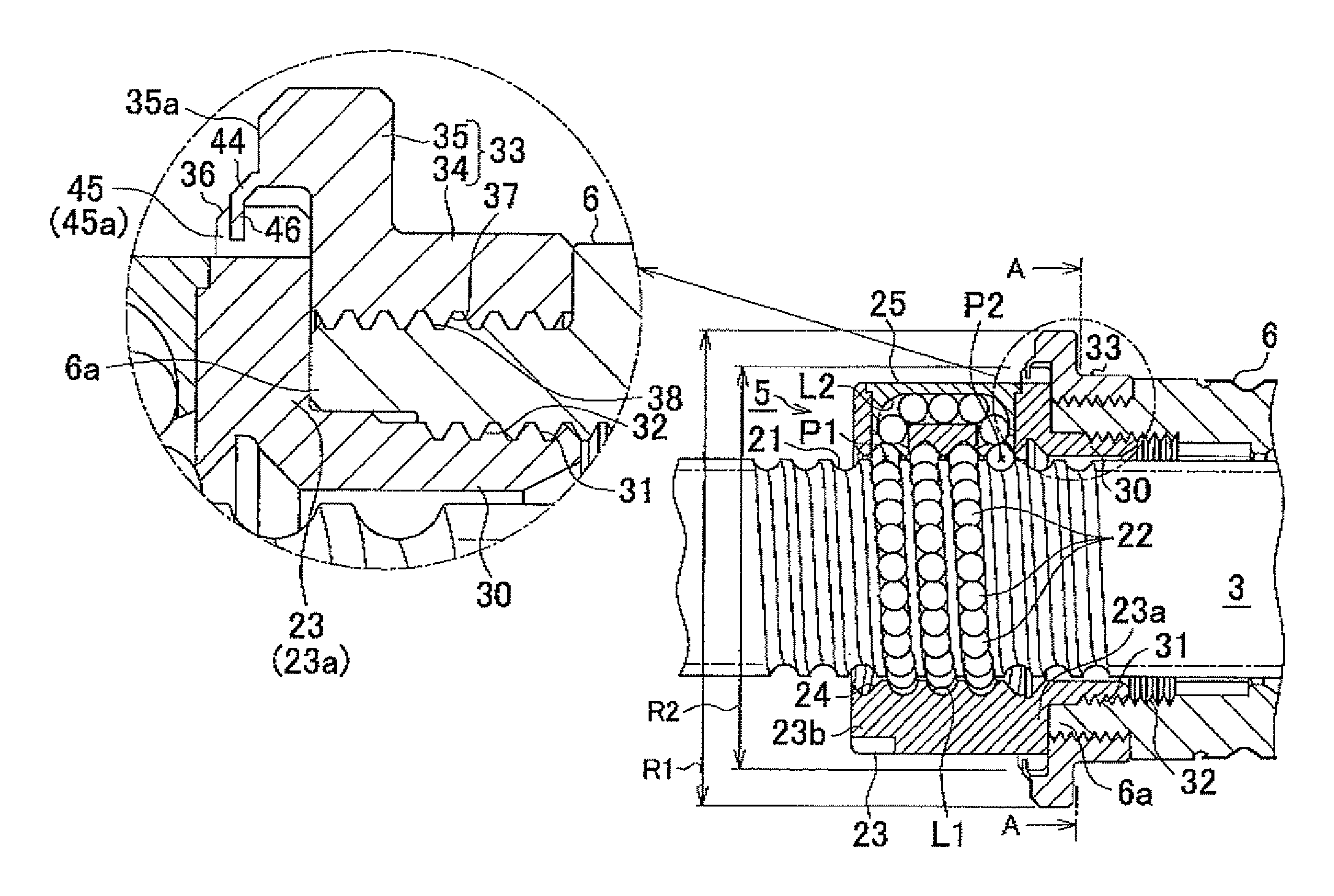
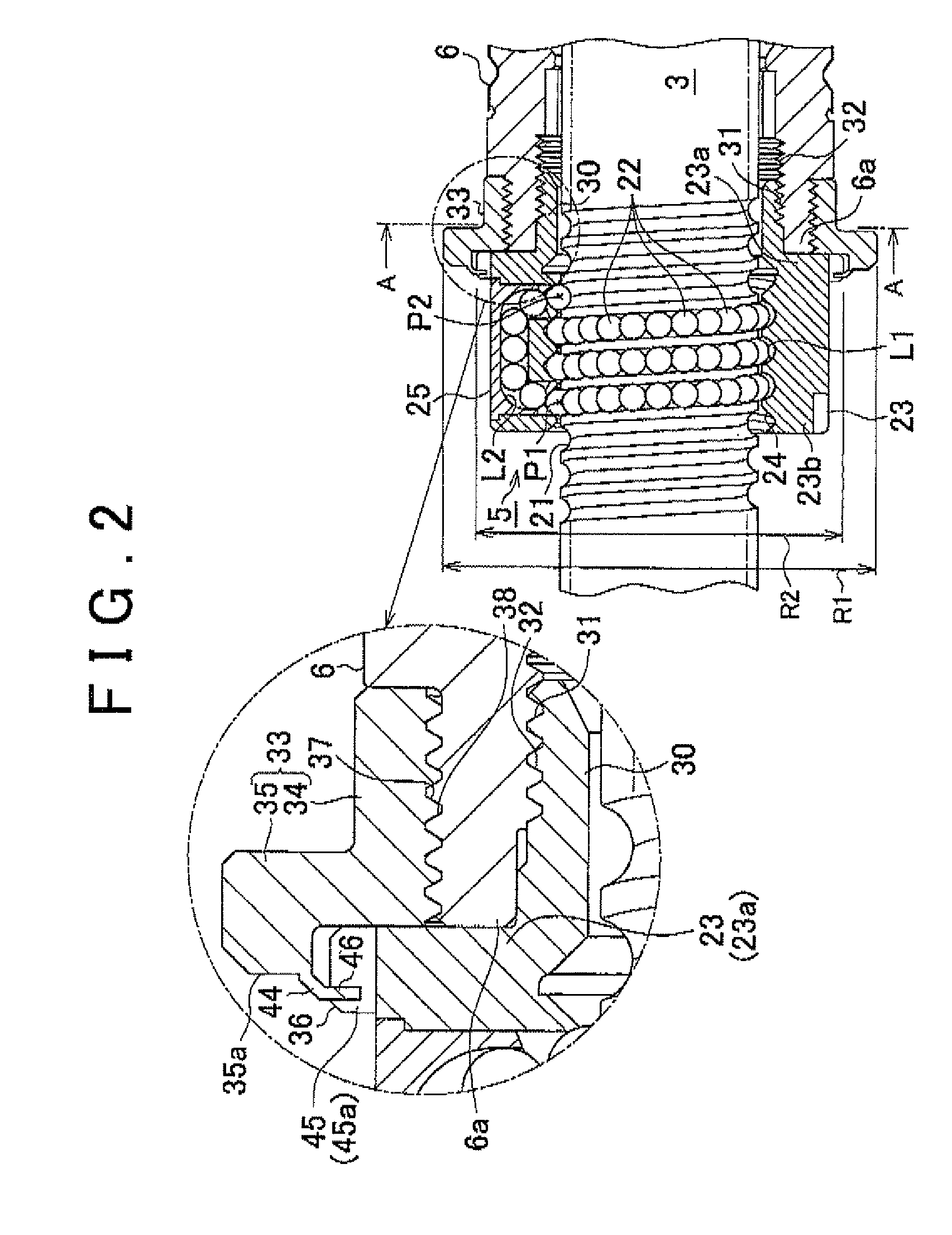
[0131]A structure for securing the ball screw nut 23 to the motor shaft 6 in the EPS 1 will be described below. As shown in FIGS. 26 to 29, the hollow threaded shaft 30 that extends in the axial direction is formed at the axial end portion 23a (right end portion in FIG. 27) of the ball screw nut 23. In addition, the threaded portion 32 that corresponds to the threaded portion 31 formed in the outer periphery of the threaded shaft 30 is formed in the inner periphery of the motor shaft 6. When the threaded portion 31 of the threaded shaft 30 formed at the axial end portion 23a of the ball screw nut 23 is screwed to the threaded portion 32 formed in the inner periphery of the motor shaft 6, the ball screw nut 23 is secured to the axial end portion 6a of the motor shaft 6.

[0132]The flange member 33 is fitted to the outer periphery of the axial end portion 6a of the motor shaft 6. The flange member 33 is larger in outer diameter than the ball screw nut 23. By restricting the rotation of...


PUM


Abstract

In an electric power steering system, multiple cutouts (45) are formed in a flange portion (36) formed on an axial end portion (23a) of a ball screw nut (23) of a ball screw device that drives a rack shaft. In addition, a motor shaft (6) has a thin-plate portion (44) that extends on the radially outer side of the ball screw nut (23). When the thin-plate portion (44) that extends from the motor shaft (6) is swaged into the cutouts (45) that serve as engagement recesses that have side walls in the circumferential direction, the rotation of the ball screw nut (23) relative to the motor shaft (6) is restricted.

Description

INCORPORATION BY REFERENCE[0001]The disclosures of Japanese Patent Application No. 2009-199786 filed on Aug. 31, 2009 and Japanese Patent Application No. 2009-278195 filed on Dec. 8, 2009, each including the specification, drawings and abstract, are incorporated herein by reference in their entireties.BACKGROUND OF THE INVENTION[0002]1. Field of the Invention[0003]The invention relates to an electric power steering system that includes a ball screw device.[0004]2. Description of the Related Art[0005]There is a rack-assist-type electric power steering system (EPS) that converts the rotation of a motor shaft, through which a rack shaft passes and which is rotated by a motor, into axial movement of the rack shaft using a ball screw device to supply assist force to a steering system.[0006]In the EPS described above, the ball screw device is formed by arranging a plurality of balls between a ball screw nut secured to the motor shaft and a threaded portion formed in the rack shaft. When a...

Claims


Application Information

Patent Timeline
Patent Type & Authority Patents(United States)
IPC IPC(8): B62D5/04
CPCB62D5/0427B62D5/0448
Inventor ASAKURA, TOSHIHIROHARA, TAKASHIASAKURA, MASAYOSHI
Owner JTEKT CORP
Why Eureka
Try Eureka