
Turning insert, a tool part, a method as well as a machine tool for chip-cutting metal machining

a technology of turning inserts and metal machining, which is applied in the direction of cutting inserts, manufacturing tools, shaping cutters, etc., can solve the problems of affecting the service life negatively, high heat generation of this area, and large wear of the same area, so as to achieve the effect of high rotation speed of turning inserts, high friction, and advantageous rotation speed

Inactive Publication Date: 2014-07-15
SANDVIK INTELLECTUAL PROPERTY AB
View PDF15 Cites 5 Cited by
  • Summary
  • Abstract
  • Description
  • Claims
  • Application Information

AI Technical Summary

Benefits of technology

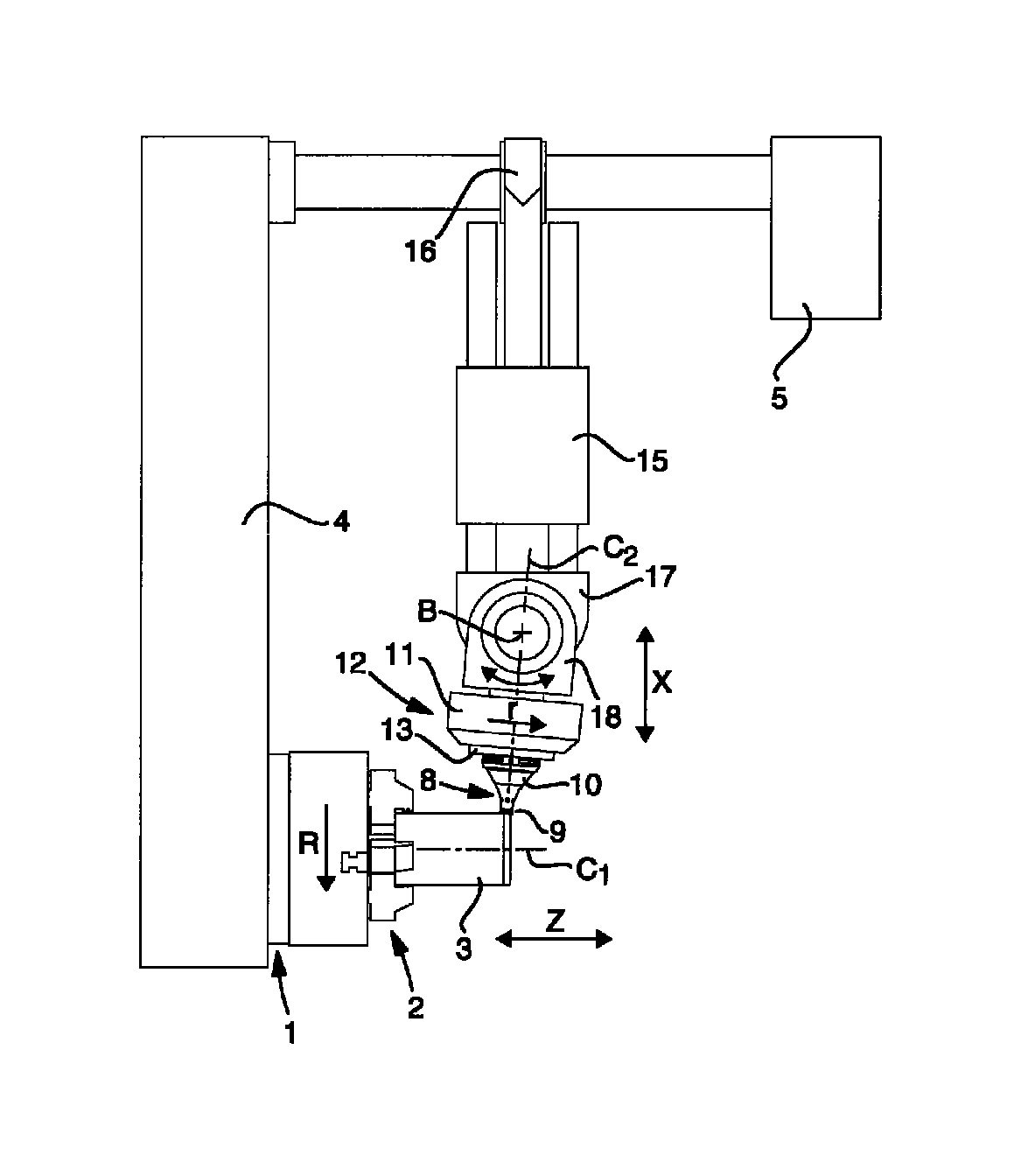
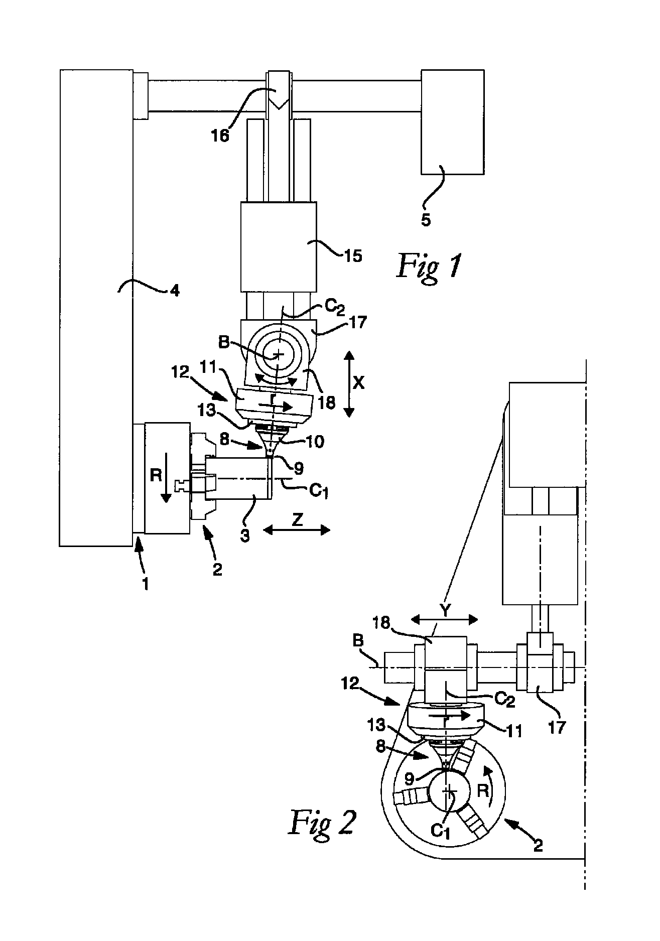
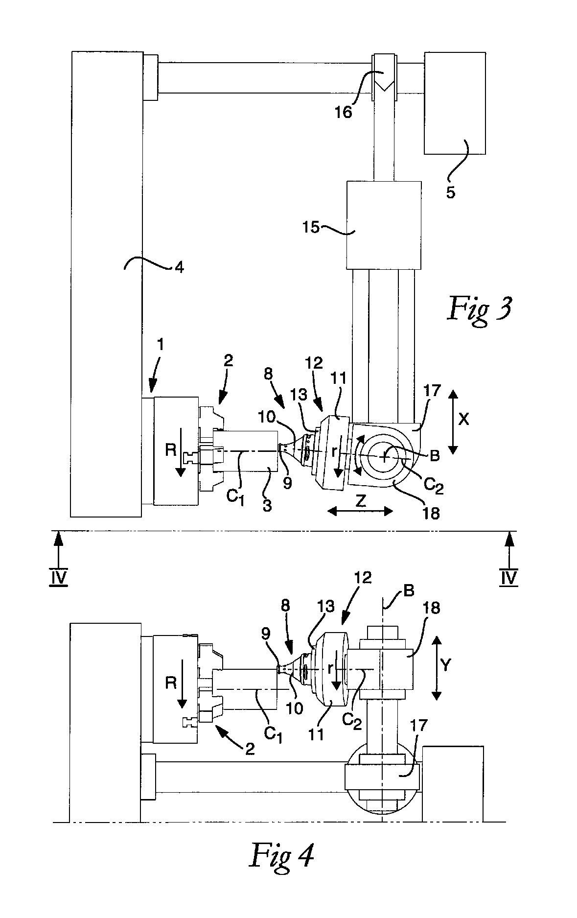
[0010]By such a turning insert, which rotates around its own tool axis, an advantage is achieved that a new active cutting edge is fed continuously up to engagement with the workpiece. Accordingly, each part of the active cutting edge will only be in engagement with the workpiece during a relatively short time of the machining. During the time when the cutting edge is not in engagement with the workpiece, it can cool down, whereby the temperature of the cutting edge can be kept on a relatively low level. The fact that the envelope surface of the turning insert forms the chip surface entails that the tool can be made relatively short since the tool extends away from the workpiece. The risk of parts of the tool contacting the workpiece during the machining is therefore obviated. This is particularly advantageous in order to allow machining of workpieces of a large diameter and to allow face turning. The machining is also facilitated by the tool being relatively short along its tool axis, which means that problems of vibrations and unbalances can be kept on a low level.
[0018]The chip breaking means may include a number of elevations that extend outward in respect of the tool axis, each one of which includes a limiting surface that forms a cutting edge where the limiting surface meets the envelope surface of the second portion. This limiting surface extends outward in respect of the rotationally symmetrical shape of the first portion. The limiting surface may be plane, concave, convex or conical. The limiting surface may be parallel to, or essentially parallel to, the plane. The cutting edge that is formed by the limiting surface and the envelope surface and that will hit the chip contributes efficiently in breaking the chip by a cutting and / or shearing machining of the chip.
[0019]The second portion may have a rotationally symmetrical second extension. The chip breaking means may then include at least one of a circumferential notch that extends inward in respect of the tool axis and a circumferential elevation that extends outward in respect of the tool axis. Also such a rotationally symmetrical chip breaking elevation or recess may contribute to an efficient breaking of the chip.
[0026]The machine tool may include a control appliance arranged to control the second driving member with the purpose of affecting the second speed of rotation. The speed of rotation of the turning insert may advantageously be controlled to achieve different properties of the metal machining. A relatively high speed of rotation of the turning insert gives a higher friction and more heat. In such a way, a liquid state, i.e., local melting of the workpiece, can be achieved upon the proper chip formation. A relatively low speed of rotation can, in combination with the non-rotationally symmetrical shape, contribute to an efficient chip breaking.

Problems solved by technology

This means that the heating of this area becomes high and that the wear of the same area thereby becomes great.
This in turn affects the service life negatively.
The technique disclosed in the above-mentioned U.S. Pat. No. 7,156,006 has the disadvantage that the tool, which rotates around its own center axis, has to be relatively long and slender, particularly in those cases when the workpiece has a large diameter.
For this reason, it is also difficult to face turn end surfaces of workpieces using the technique disclosed in U.S. Pat. No. 7,156,006 and U.S. Pat. No. 7,325,471, particularly if the radius of the end surface is longer than the front slender part of the tool.

Method used


Image

  • Turning insert, a tool part, a method as well as a machine tool for chip-cutting metal machining
  • Turning insert, a tool part, a method as well as a machine tool for chip-cutting metal machining
  • Turning insert, a tool part, a method as well as a machine tool for chip-cutting metal machining

Examples


first embodiment

[0062]FIGS. 5-8 show the turning insert 9. The turning insert 9 is formed as a cutting insert having a fastening hole 25 for the receipt of a fastening element, for instance a screw 38, see FIG. 20, for fastening the turning insert 9 in the tool holder 10. The fastening hole 25 extends through the front surface 21 and the turning insert 9.

[0063]The first portion 24a of the chip surface 24 has a rotationally symmetrical first extension and, in the first embodiment, a concave shape as seen in a cross-sectional plane comprising the tool axis C2, see FIGS. 7 and 8. In the first embodiment, the angle α is measured in the immediate vicinity of the cutting edge 23 and less than 90° in respect of the first portion 24a. The angle α may be 40-80°.

[0064]The chip breaking means include the circumferential second portion 24b of the chip surface 24. In that connection, in the first embodiment, the second portion 24b has a non-rotationally symmetrical second extension that forms at least part of t...

fourth embodiment

[0069]The fourth embodiment also differs from the earlier embodiments in that the turning insert 9 has a tapering fastening pin 33 formed to be inserted and be fastened in a corresponding opening 34 of the tool holder 10. As is seen in FIG. 19, the fastening pin 33 and the opening 34 has each a thread, which are in engagement with each other when the turning insert 9 is fixed in the tool holder 10.

[0070]FIG. 20 shows a tool 8 having a tool holder 10 and a turning insert 9 according to the first embodiment. The turning insert 9 is detachably mounted on the tool holder 10 by a fixing screw 38.

[0071]FIGS. 21 and 22 illustrate a fifth embodiment of a turning insert 9, wherein the chip breaking means include a circumferential notch 35 that extends inward in respect of the tool axis C2, and a circumferential elevation 36 that extends outward in respect of the tool axis C2. Such a rotationally symmetrical shape of the chip breaking means may advantageously be provided on the second portion...

sixth embodiment

[0072]FIGS. 23-26 show a turning insert 9 which is an integrated part of a tool part 8′ that is mounted in the tool 8. The turning insert 9 is formed in the tool part 8′, for instance by machining of the tool part 8′ for the creation of the cutting edge 23 and other details. The tool part 8′ is formed as a cylindrical body having two ends. One or both ends may be provided with a respective integrated turning insert 9. In the embodiment illustrated, the tool part 8′ is formed as a solid, or essentially solid, body. The tool part 8′ may, however, include one or more cooling ducts (not shown) that extend through the solid body.

[0073]In the sixth embodiment, the tool 8 has a tool holder 10 that is formed as a chuck-like holder or as a tool chuck. The tool holder 10 includes a cylindrical, or essentially cylindrical, cavity for the receipt of the tool part 8′ including the turning insert(s) 9 in such a way that one turning insert 9 is outside the cavity. The tool holder 10 in the sixth ...


PUM

PropertyMeasurementUnit
angleaaaaaaaaaa
angleaaaaaaaaaa
angleaaaaaaaaaa

Abstract

A turning insert formed for chip-cutting metal machining of a workpiece that rotates in a direction of rotation at a first speed of rotation around a workpiece axis, the turning insert including a front surface, an envelope surface, and a circular cutting edge located where the front surface meets the envelope surface. The cutting edge extends around the front surface and lays in a plane that forms an angle α with the envelope surface. A tool axis extends through the turning insert in a normal direction in respect of the plane, and the turning insert, during the chip-cutting metal machining, is formed to rotate around the tool axis at a second speed of rotation. The envelope surface forms a chip surface and is arranged to meet chips formed in the chip-cutting metal machining, and the chip surface includes chip breaking means.

Description

[0001]This application claims priority under 35 U.S.C. §119 to Swedish Patent Application No. 1050140-1, filed on Feb. 12, 2010, which is incorporated by reference herein in its entirety.FIELD OF THE INVENTION[0002]The present invention relates generally to chip-cutting metal machining by turning. More precisely, the invention relates to a turning insert formed for chip-cutting metal machining of a workpiece that rotates in a first direction of rotation at a first speed of rotation around a workpiece axis. The turning insert includes a front surface, an envelope surface and a circular cutting edge located where the front surface meets the envelope surface, the cutting edge extending around the front surface and lying in a plane that forms an angle α with the envelope surface. A tool axis extends through the turning insert in a normal direction in respect of the plane, and the turning insert, during the chip-cutting metal machining, is formed to rotate around the tool axis at a secon...

Claims


Application Information

Patent Timeline
Patent Type & Authority Patents(United States)
IPC IPC(8): B23B27/16B23B27/12
CPCY10T407/20Y10T407/1924B23B2210/06Y10T82/2572Y10T407/235Y10T82/2529Y10T407/23B23B27/14B23B2200/369B23B27/12B23B27/145Y10T82/10B23B5/00B23B27/16B23B27/22
Inventor SJOO, STURE
Owner SANDVIK INTELLECTUAL PROPERTY AB
Learn More