
Oil drain system bypass

a technology of bypassing oil and oil draining system, which is applied in the direction of machine/engine, engine revolution, lubrication of auxiliaries, etc., can solve the problems of temperature of engine oil contributing to the fuel consumption and emissions of internal combustion engines, and the possibility of disassembly of bypass oil lines, etc., and achieves the effect of contributing to the fuel economy of vehicles

Inactive Publication Date: 2014-06-10
FORD GLOBAL TECH LLC
View PDF21 Cites 0 Cited by
  • Summary
  • Abstract
  • Description
  • Claims
  • Application Information

AI Technical Summary

Benefits of technology

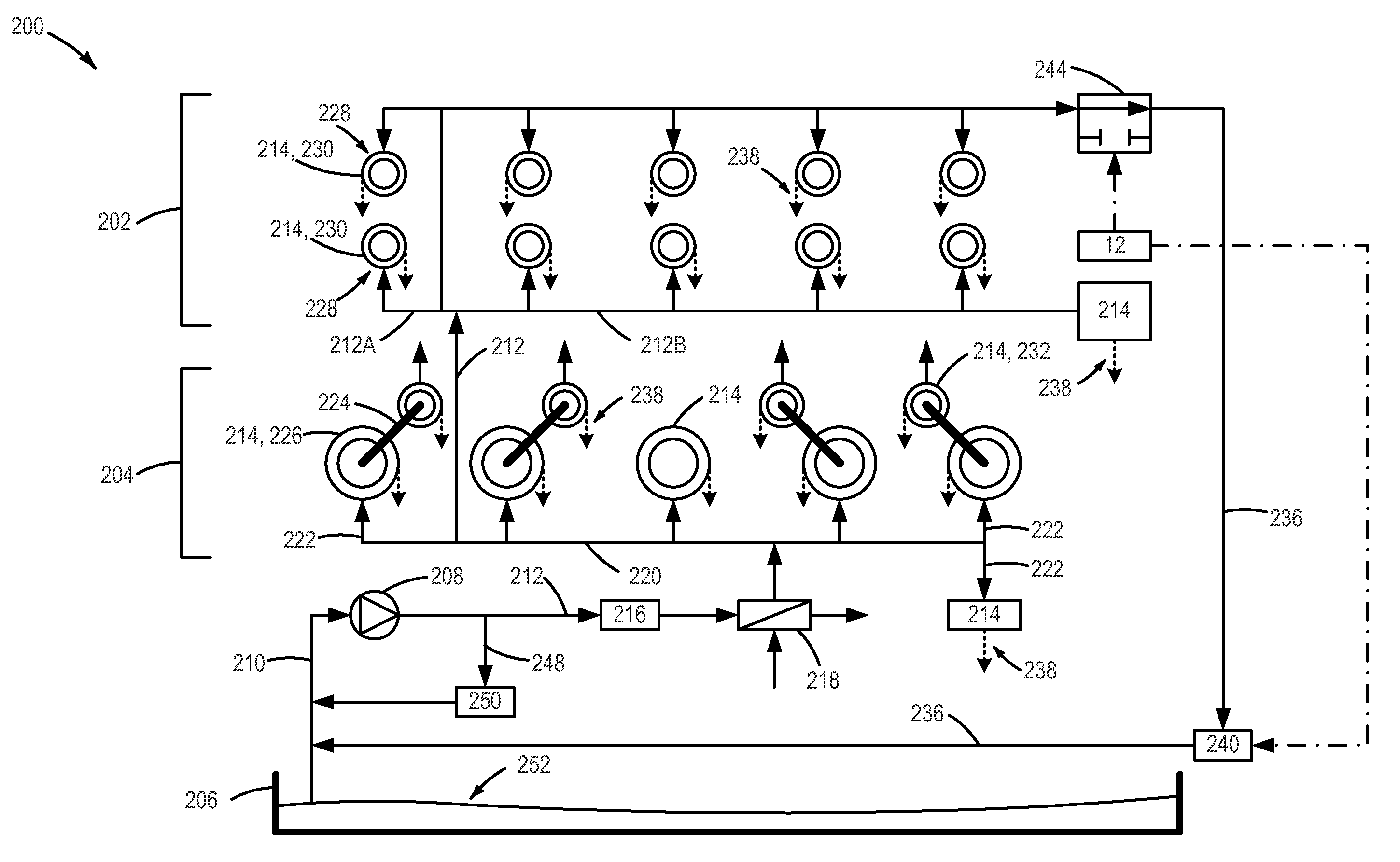
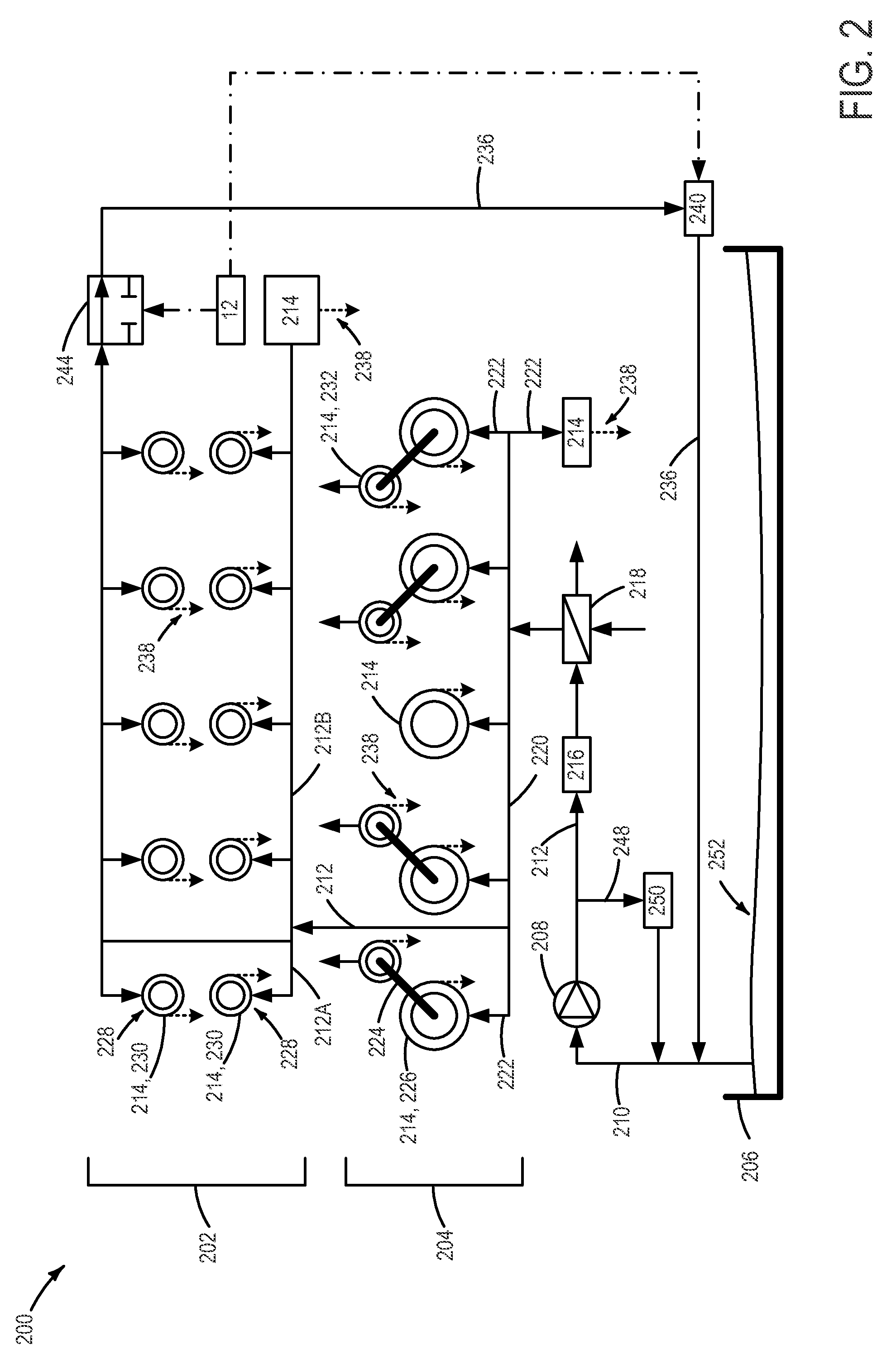
The patent describes a system for heating engine oil in an internal combustion engine. The system includes a higher pressure oil pump that supplies engine oil to various engine components before being returned to the sump. The oil is heated by using the engine's own heat and friction from the components. The system also includes a bypass line that allows some of the oil to be routed to the engine components before being returned to the sump. This allows the oil to heat up faster and reduces fuel consumption and emissions. The system can be used in both diesel and spark-ignition engines.

Problems solved by technology

Thus, the temperature of the engine oil contributes to the fuel consumption and emissions of the internal combustion engine.
Then, once sufficient warm-up has occurred where substantially all of the engine oil, including oil in the sump, has reached a desired operating temperature, the bypass oil line may be disabled.

Method used


Image

  • Oil drain system bypass
  • Oil drain system bypass
  • Oil drain system bypass

Examples


Embodiment Construction

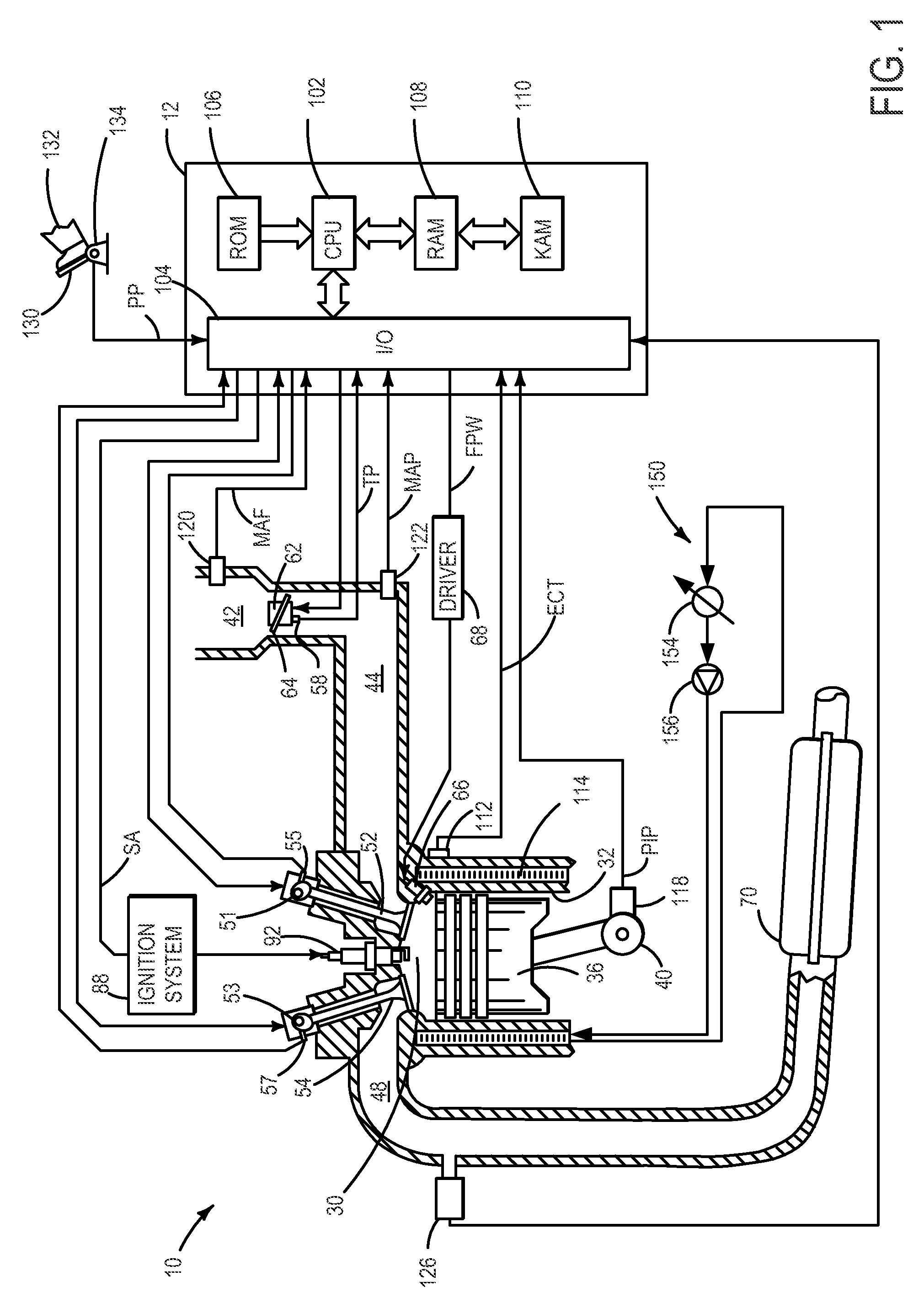
[0012]An internal combustion engine may be used as a drive for motor vehicles. Within the context of the present disclosure, “internal combustion engine” encompasses diesel engines, spark-ignition engines, and hybrid internal combustion engines (e.g., an internal combustion engine operated with a hybrid combustion process). In some embodiments, the engine may be coupled to an electric motor / battery system in a hybrid vehicle. Non-limiting examples of hybrid vehicles may have a parallel configuration, a series configuration, or any suitable variation or combination thereof.

[0013]Internal combustion engines have a cylinder block and a cylinder head that are united to form a cylinder for combusting fuel. Referring to FIG. 1, internal combustion engine 10 comprises a plurality of cylinders, one cylinder of which is shown in FIG. 1. Engine 10 includes combustion chamber 30 and cylinder walls 32 with piston 36 positioned therein and connected to crankshaft 40. Engine 10 is controlled by e...


PUM


Abstract

A system and method are provided for increasing heating of engine oil during a cold start. In one example, engine oil is returned directly to the oil pump inlet, thus bypassing the sump. In this way, a smaller volume of oil receives more heat and is used for lubricating engine components during a cold start, thus providing reduced friction earlier than otherwise possible.

Description

CROSS-REFERENCE TO RELATED APPLICATIONS[0001]This application claims priority to German Patent Application Serial Number 10 2010 027 816.5, titled “INTERNAL COMBUSTION ENGINE WITH OIL CIRCUIT AND METHOD FOR HEATING THE ENGINE OIL OF AN INTERNAL COMBUSTION ENGINE OF SAID TYPE” and filed on Apr. 15, 2010, the entire disclosure of which is hereby incorporated by reference for all purposes.FIELD[0002]The present description relates to a system for heating engine oil.BACKGROUND AND SUMMARY[0003]Friction in lubricated engine bearings, such as camshaft bearings, contributes to a vehicle's fuel economy. The friction depends, at least in part, on engine oil viscosity, which is a function of engine oil temperature. Thus, the temperature of the engine oil contributes to the fuel consumption and emissions of the internal combustion engine.[0004]Oil systems may be provided where oil is drawn from a sump and provided to various engine components before being returned to the sump. While various ap...

Claims


Application Information

Patent Timeline
Patent Type & Authority Patents(United States)
IPC IPC(8): F01M1/02F01M11/02F01M1/16
CPCF01M2250/64F01M2250/60F01M1/16F01M9/10
Inventor SPRINGER, MORITZ KLAUSQUIX, HANS GUENTERMEHRING, JAN
Owner FORD GLOBAL TECH LLC
Learn More