Evaporated fuel treating device
a technology of evaporation fuel and treating device, which is applied in the direction of liquid fuel feeder, combustion air/fuel air treatment, machines/engines, etc., can solve the problems of deteriorating refueling performance, and achieve the effect of reducing the l/d ratio of a portion, reducing the deterioration of refueling performance, and increasing the effective cross-section
- Summary
- Abstract
- Description
- Claims
- Application Information
AI Technical Summary
Benefits of technology
Problems solved by technology
Method used
Image
Examples
embodiment 1
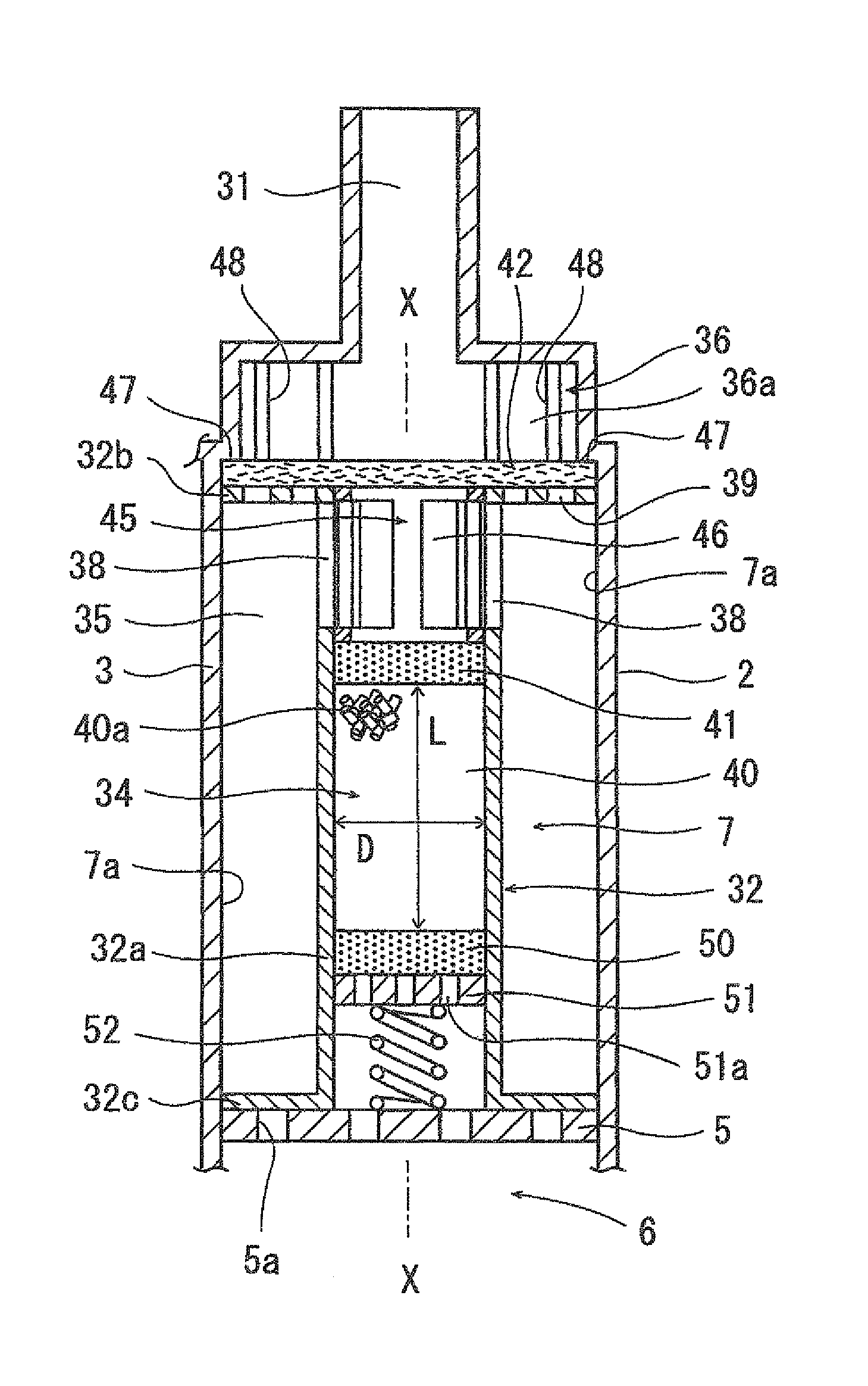
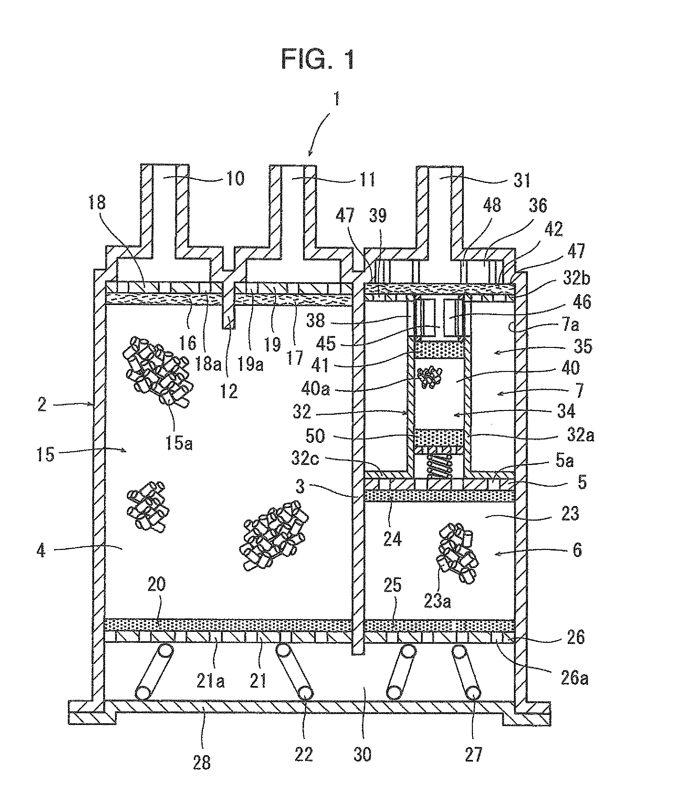
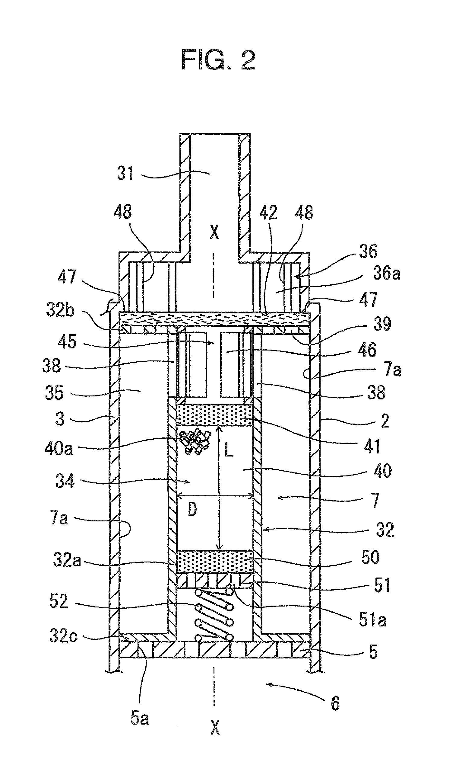
[0035]FIGS. 1 to 7B illustrate Embodiment 1 according to the present invention.
[0036]FIG. 1 is a diagram schematically illustrating an evaporated fuel treating device 1. The evaporated fuel treating device 1 has a case 2. In the following description, the upper end in FIG. 1 will be defined as the top, the lower end will be defined as the bottom, and the direction orthogonal to the vertical direction will be defined as a horizontal direction.
[0037]The case 2 has therein a partition wall 3 vertically arranged downward from the upper end of the case 2. The interior of the case 2 is partitioned by the partition wall 3 into two spaces in the horizontal direction, the two spaces being in communication through a space 30 under the lower end of the partition wall 3. Further, the left space in FIG. 1 constitutes a first chamber 4, and the right space in FIG. 1 is divided into two compartments in the vertical direction by a plate 5 arranged in the horizontal direction, the lower chamber bein...
embodiment 2
[0065]In Embodiment 1 described above, three chambers 4, 6 and 7 have been formed in the case 2 and each of the chambers has been provided with the adsorbent layer to construct the evaporated fuel treating device 1. The present invention may be applied to any evaporated fuel treating device as long as the case has at least an atmospheric port, the case has therein at least one chamber in communication with the atmospheric port and the interior of a chamber closest to the atmospheric port is divided into a first compartment 34, a second compartment 35, and a third compartment 36 as with the aforesaid Embodiment 1 by using the same partition member as the partition member 32 of the aforesaid Embodiment 1 so as to provide the same construction as that of the third chamber 7 in the aforesaid Embodiment 1.
[0066]For example, as illustrated in FIG. 8, the second chamber 6 may have an air layer rather than providing the second adsorbent layer 23 in the second chamber 6. Further, as illustra...
embodiment 3
[0069]In Embodiments 1 and 2 described above, the third chamber 7 has been formed such that its cross-section orthogonal to the axis X-X of the partition member 32 is rectangular, the contours of the separating walls 32b and 32c of the partition member 32 have been rectangular, the peripheral wall 32a has been shaped to be cylindrical, and the axis X-X of the peripheral wall 32a has been set to be substantially the same as the axis of the third chamber 7. However, the inner surface of the third chamber 7 may have any shape and the separating walls 32b and 32c of the partition member 32 may have contours matching the inner contour of the third chamber 7, as long as the third chamber 7 is in communication with the atmospheric port 31. Similarly, the peripheral wall 32a may have any shape as long as the first compartment 34 is formed on the inner side of the peripheral wall 32a, the second compartment 35 is formed between the peripheral wall 32a and the case 2, and the first communicat...
PUM
 Abstract
Description
Claims
Application Information
 - R&D
- Intellectual Property
- Life Sciences
- Materials
- Tech Scout
- Unparalleled Data Quality
- Higher Quality Content
- 60% Fewer Hallucinations
Browse by: Latest US Patents, China's latest patents, Technical Efficacy Thesaurus, Application Domain, Technology Topic, Popular Technical Reports.
© 2025 PatSnap. All rights reserved.Legal|Privacy policy|Modern Slavery Act Transparency Statement|Sitemap|About US| Contact US: help@patsnap.com


