
System and method of providing communications in a wireless power transfer system

a wireless power transfer and communication system technology, applied in the field of wireless power transfer systems, can solve the problems of affecting performance, presenting other undesirable issues, and disrupting wireless power communication, and achieves simple and effective systems and methods, improve reliability, and improve signal to noise ratio

Active Publication Date: 2014-05-20
PHILIPS IP VENTURES BV
View PDF54 Cites 58 Cited by
  • Summary
  • Abstract
  • Description
  • Claims
  • Application Information

AI Technical Summary

Benefits of technology

The present invention provides a way to transmit signals using a variable frequency carrier signal. This method improves reliability by using multiple modulations for each bit and averaging out any defects in the modulations. This also results in a more consistent load between high and low signals. In some applications, timeslicing is used to cancel out the base drive waveform, resulting in a higher signal-to-noise ratio. Overall, this invention provides a simple and effective way to transmit signals over an inductive field.

Problems solved by technology

In a further example, the presence of parasitic metal in range of the wireless power supply may affect performance or present other undesirable issues.
Wireless power communications can be disrupted if the device being powered presents a noisy load.
For example, changes in the amount of power consumed in a device may change the impedance of the remote device.
These changes in impedance may create the appearance of data when none exists or they may corrupt legitimate data.
The power supply can be especially susceptible to noise that occurs at that same frequency as the data communications.
For example, it is possible that load fluctuations occurring while data is being transmitted will mask the legitimate data.
Although the power supply should eventually determine that the data packet is not legitimate, the power supply may be occupied with the illegitimate packet, which would delay its ability to recognize legitimate data.
This can be particularly problematic when the remote device battery is depleted.

Method used


Image

  • System and method of providing communications in a wireless power transfer system
  • System and method of providing communications in a wireless power transfer system
  • System and method of providing communications in a wireless power transfer system

Examples


Embodiment Construction

I. Overview

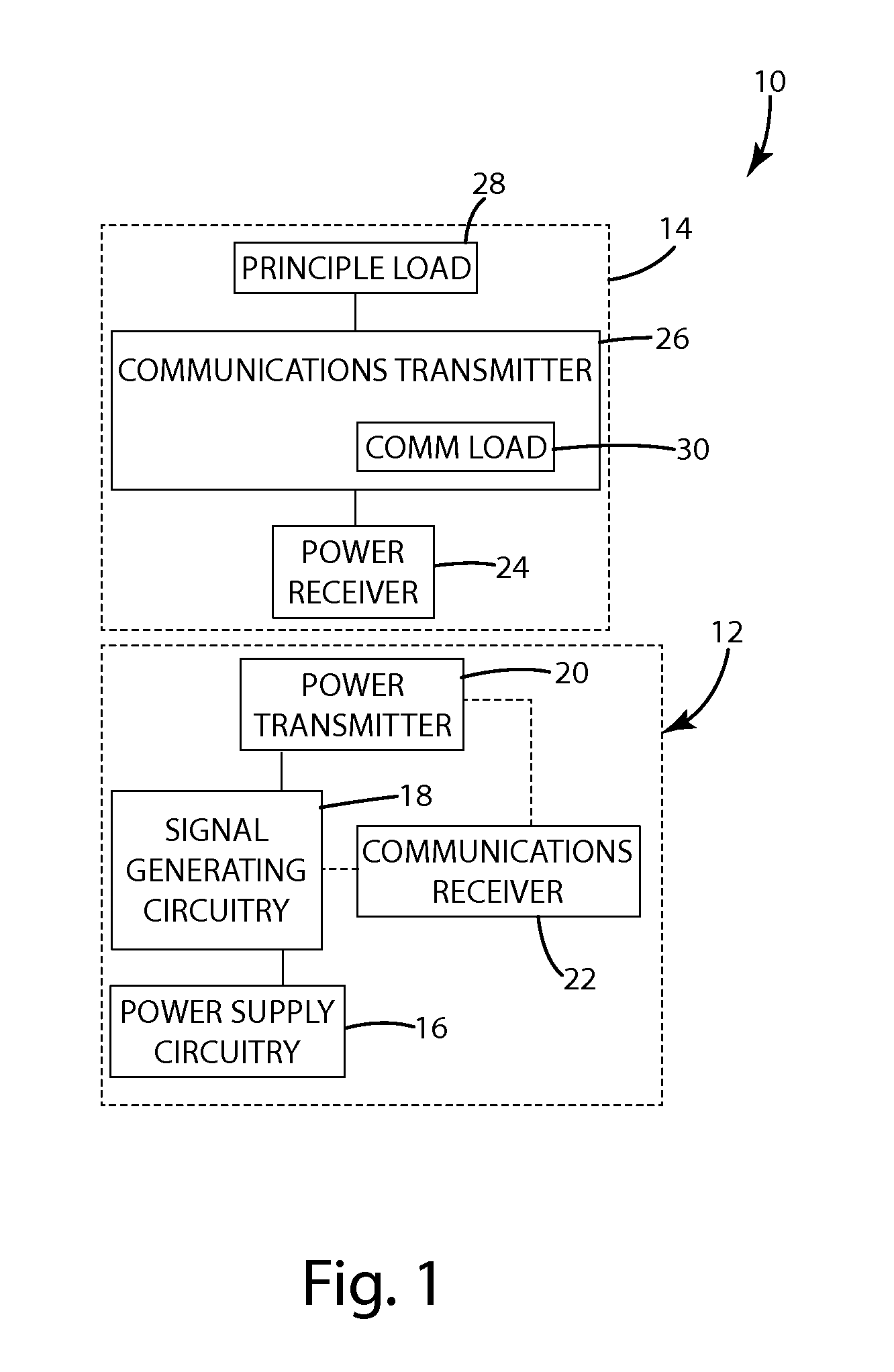
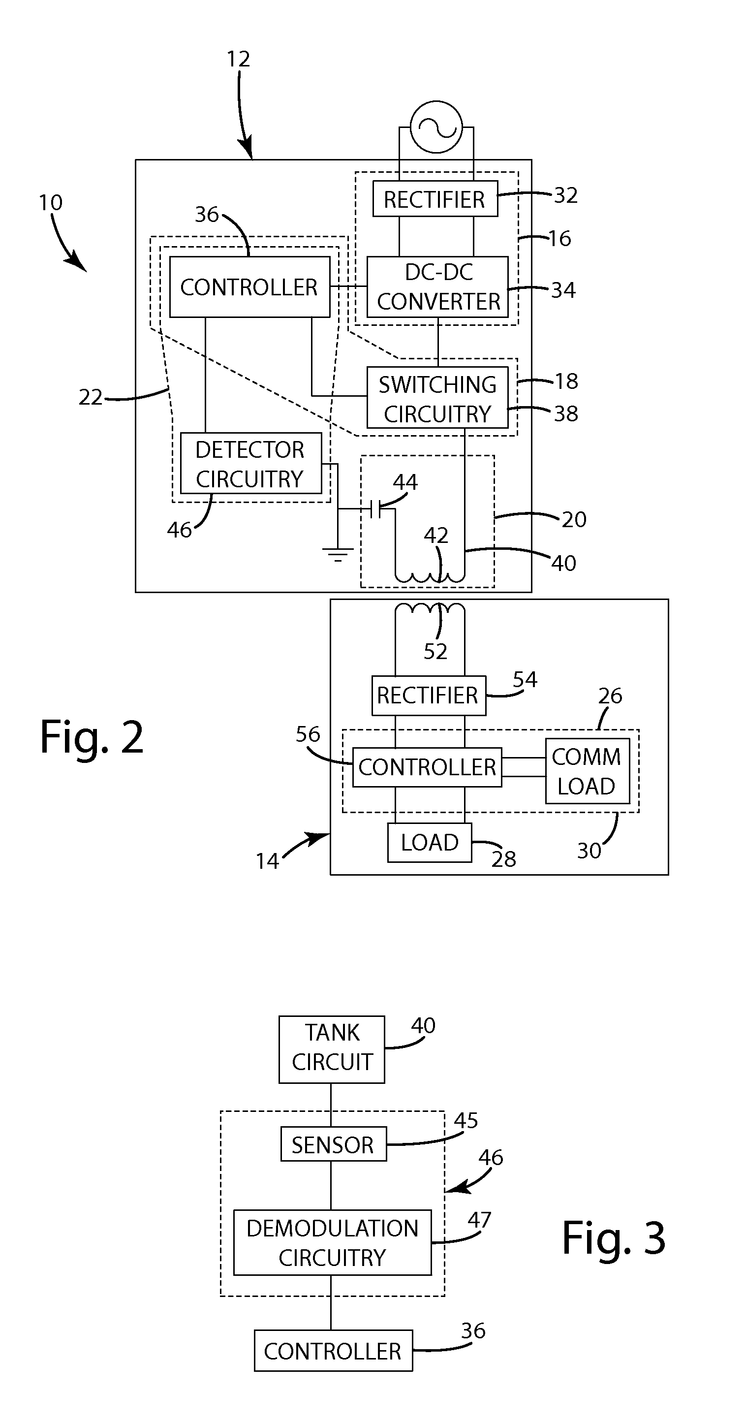
[0035]A wireless power transfer system in accordance with an embodiment of the present invention is shown in FIG. 1. The wireless power transfer system 10 generally includes a wireless power supply 12 and a remote device 14. The wireless power supply 12 is capable of wirelessly supplying power to the remote device 14 by an inductive field that can be coupled to the remote device 14. The remote device 14 is configured to send communications to the wireless power supply 12 by overlaying the communications onto the inductive field produced by the wireless power supply 12. The wireless power supply 12 generally includes power supply circuitry 16, signal generating circuitry 18, a power transmitter20 and a wireless communication receiver 22. The wireless communication receiver 22 is configured to receive communication from the remote device 14 via backscatter modulation. The remote device 14 generally includes a power receiver 24, a communications transmitter 26 and a principl...


PUM


Abstract

A communication system that uses keyed modulation to encode fixed frequency communications on a variable frequency power transmission signal in which a single communication bit is represented by a plurality of modulations. To provide a fixed communication rate, the number of modulations associated with each bit is dynamic varying as a function of the ratio of the communication frequency to the carrier signal frequency. In one embodiment, the present invention provides dynamic phase-shift-keyed modulation in which communications are generated by toggling a load at a rate that is a fraction of the power transfer frequency. In another embodiment, the present invention provides communication by toggling a load in the communication transmitter at a rate that is phase locked and at a harmonic of the power transfer frequency. In yet another embodiment, the present invention provides frequency-shift-keyed modulation, including, for example, modulation at one of two different frequencies.

Description

BACKGROUND OF THE INVENTION[0001]The present invention relates to wireless power transfer systems, and more particularly to systems and methods for providing communications in a wireless power transfer system.[0002]Many conventional wireless power supply systems rely on inductive power transfer to convey electrical power without wires. A typical inductive power transfer system includes an inductive power supply that uses a primary coil to wirelessly transfer energy in the form of a varying electromagnetic field and a remote device that uses a secondary coil to convert the energy in the electromagnetic field into electrical power. Recognizing the potential benefits, some developers have focused on producing wireless power supply systems with adaptive control systems capable of adapting to maximize efficiency and provide appropriate operation to a variety of different types of devices under a wide range of circumstances. Adaptive control systems may vary operating parameters such as r...

Claims


Application Information

Patent Timeline
Patent Type & Authority Patents(United States)
IPC IPC(8): H04L27/06H03K9/00H04B5/48
CPCH04B5/0081H04B5/0031H04B5/0037H04B5/26H04B5/79H04B5/266H04B5/45H03K7/10H02J50/80H02J50/12H04B5/72
Inventor NORCONK, MATTHEW J.SCHWANNECKE, JOSHUA K.MOORE, COLIN J.TAYLOR, JOSHUA B.KUYVENHOVEN, NEIL W.LIFF, DALE R.AMISTADI, JASON L.GRUICH, ROBERT D.KELLEY, ARTHURARMSTRONG, KENNETH C.
Owner PHILIPS IP VENTURES BV
Learn More