
Microscope accessory and microplate apparatus for measuring phosphorescence and cellular oxygen consumption

a microplate and phosphorescence technology, applied in the field of microscopy, can solve the problems of contributing significantly to the cost of the system, not working well with very small wells, and not providing the necessary sensitivity to measure single-cell oxygen consumption

Active Publication Date: 2014-03-25
UNIV OF MIAMI
View PDF1 Cites 7 Cited by
  • Summary
  • Abstract
  • Description
  • Claims
  • Application Information

AI Technical Summary

Benefits of technology

The present invention provides a system and device that allows an inverted microscope with a movable x-y stage to also function as a time-resolved plate reader, for example, to measure and image phosphorescence. The microplate apparatus includes a quartz lid plate with a plurality of domes, a quartz bottom plate with a plurality of microwells, each microwell corresponding to a dome, one or more sensors located in each dome, a compressible gasket, and an inlet tube and outlet tube each in fluid communication with the microwells. The microplate apparatus may also include a stop element to prevent the lid plate from rising above a certain height. The invention also provides a method for changing a solution within the microplate apparatus. The technical effects of the invention include improved accuracy and efficiency in measuring and imaging phosphorescence, as well as improved flexibility and ease of use in changing solutions.

Problems solved by technology

Although plate reader systems, such as those used with enzyme-linked immunosorbent assay (ELISA) reader, may efficiently and accurately measure biological parameters of a sample, they have associated disadvantages.
Also, most platereaders do not work well with very small wells, for example, of less than 500-micron diameter.
However, the larger well sizes of standard microtitre plates (which are often as large as 100 to 200 microliters) fail to provide the necessary sensitivity to measure single-cell oxygen consumption.
Finally, typical methods for measuring oxygen consumption with very small samples use charge coupled device (CCD) cameras for detecting phosphorescence, which can contribute significantly to the cost of the system.
Not only are CCD cameras costly, but they can also be bulky and have a limited effective dynamic range (typically 8-10 bits).
However, an inverted microscope is not capable of taking the biological activity measurements of a plate reader, such as time-resolved phosphorescence measurements or very high accuracy quantitation of fluorescence changes with time.
One problem with relying on fluorescence, however, is that body tissue may contribute a significant amount of background fluorescence noise.

Method used


Image

  • Microscope accessory and microplate apparatus for measuring phosphorescence and cellular oxygen consumption
  • Microscope accessory and microplate apparatus for measuring phosphorescence and cellular oxygen consumption
  • Microscope accessory and microplate apparatus for measuring phosphorescence and cellular oxygen consumption

Examples


first embodiment

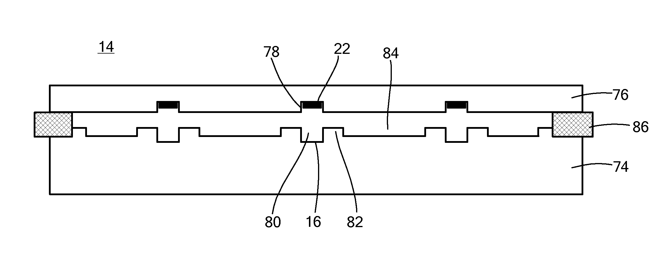
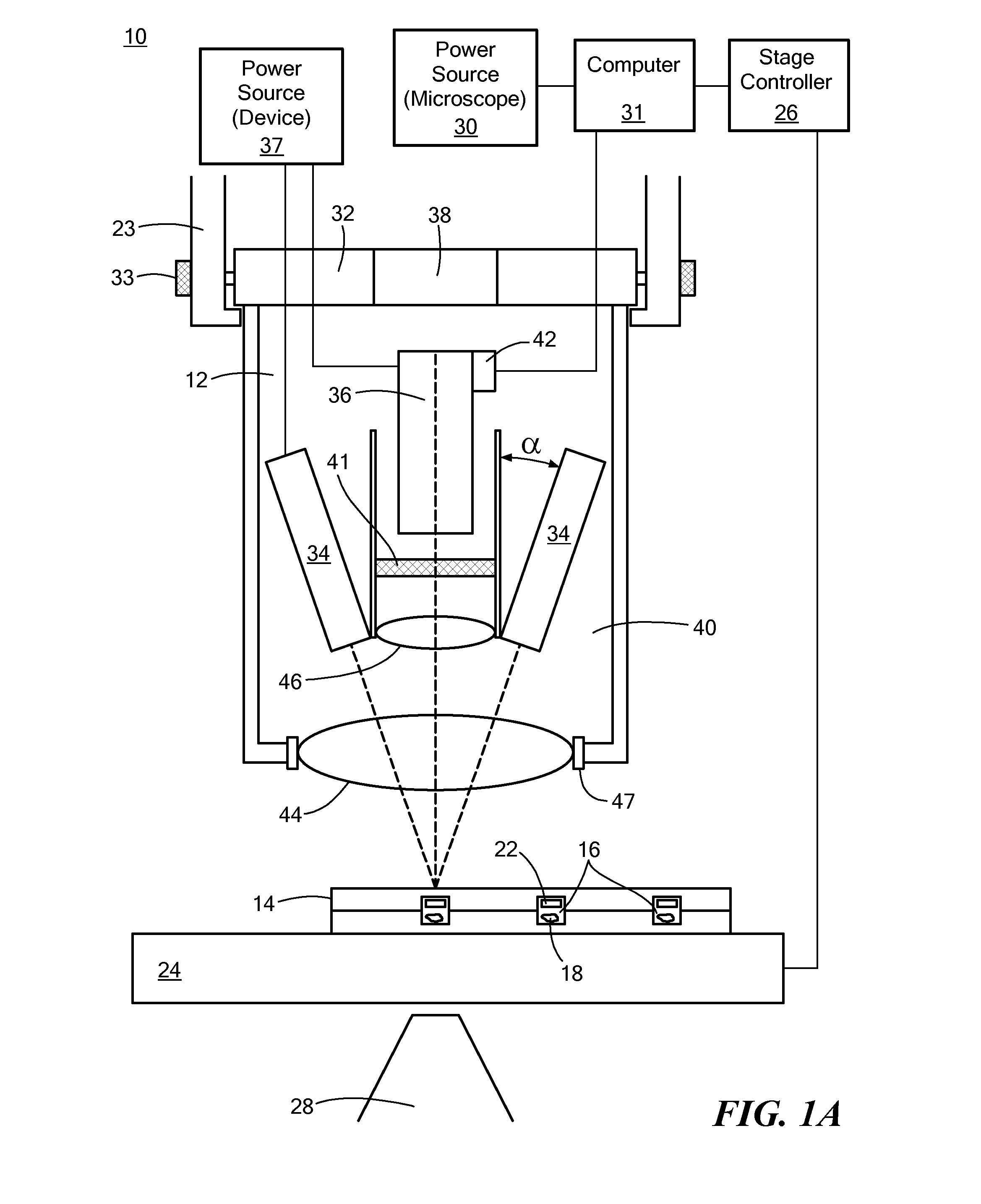
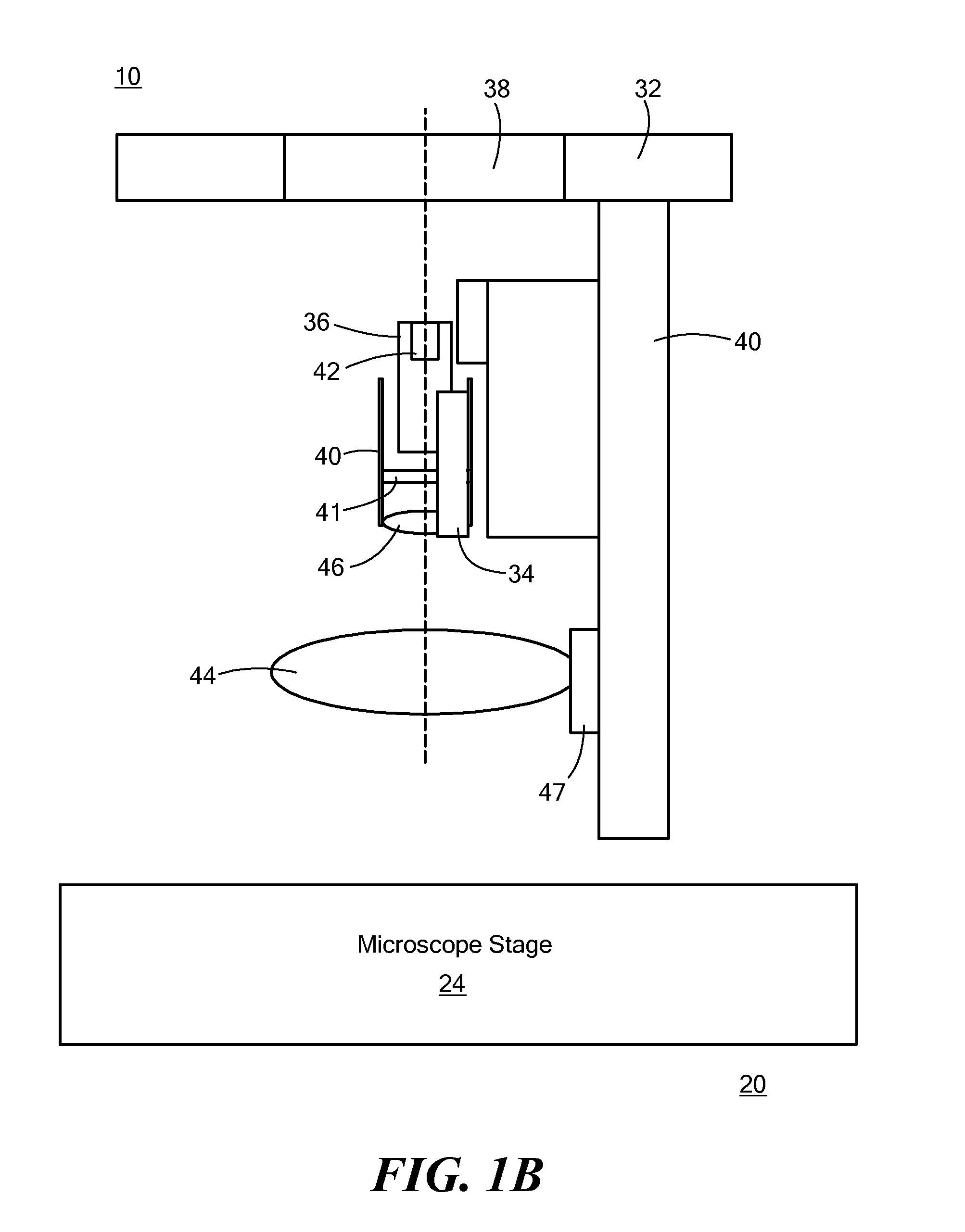
[0020]Referring now to FIG. 1A (front view) and 1B (side view), schematic representations of a system 10 and device 12 in accordance with the principles of the present invention are shown. The system 10 may generally include a phosphorescence measurement device 12, a sample holder 14 having a plurality of sample wells (or “microwells”) 16 in which one or more samples 18 may be contained, and an inverted microscope 20 for imaging the samples 18. The sample holder 14 may further include one or more sensors 22 for measuring oxygen levels, changes in pH, or other parameters.

[0021]The inverted microscope 20 may further include a condenser holder 23, a movable (for example, motorized) x-y and / or x-y-z stage 24 at a predetermined or variable distance from the condenser holder and in electrical communication with a stage controller 26. The inverted microscope 20 may further include one or more microscope objective lenses 28 for imaging the samples 18. Additionally, the inverted microscope 2...

second embodiment

[0034]Referring now to FIG. 3, a device that is sized to fit into the condenser holder is shown. The device 12 shown in FIG. 3 may be representative of the configuration of a device 12 according to FIG. 2 (second embodiment). For example, the device 12 shown in FIG. 3 may include a mounting bracket 23, an avalanche photodiode 36, an emission filter 41, a relay lens 46, a light source 34, an optical device 48, a fast photodiode 54, a lens mounting bracket 47, and a main lens 44. The device 12 may further include other elements shown and described in FIG. 2.

[0035]As an example of the phosphorescence-measuring functionality of the system 10 as shown in any of FIGS. 1A, 1B, and 2, a phosphorescence measurement cycle begins with a short (1 to 10 μsec) excitation light pulse from the one or more light sources 34 directed toward the samples 18 within the sample holder 14. The light may be sent directly to the samples 18 either through one or more lenses 44, 46 (as in FIGS. 1A and 1B) or th...


PUM

PropertyMeasurementUnit
heightaaaaaaaaaa
volumeaaaaaaaaaa
volumeaaaaaaaaaa

Abstract

A microplate apparatus having a bottom plate defining a plurality of very small microwells (for example, each having a volume of 0.02 or less) for containing sample material and a top plate defining a plurality of domes, each of which housing a sensors for measuring biological parameters, such as cellular oxygen consumption, pH changes, calcium uptake, and metabolic reduction of fluorescent dyes. The top and bottom plates may be composed of quartz. The microplate assembly may be fabricated using a method involving applying an etching solution to each of the top and bottom plates to create the domes and microwells. Additionally, etching solution may be applied to the bottom plate to create a raised lip region around each of the microwells. The etched-away areas surrounding the lip regions facilitate the changing of microwell solution without disrupting the samples.

Description

CROSS-REFERENCE TO RELATED APPLICATION[0001]This application is related to and claims priority to U.S. Provisional Patent Application Ser. No. 61 / 423,670, filed Dec. 16, 2010, entitled PLATEREADER DEVICE FOR MEASURING SINGLE CELL OXYGEN CONSUMPTION, and U.S. Provisional Patent Application Ser. No. 61 / 546,692, filed Oct. 13, 2011, entitled MICROSCOPE ACCESSORY FOR WHOLE WELL FLUORESCENCE AND TIME RESOLVED PHOSPHORESCENCE MEASUREMENTS, the entirety of both of which are incorporated herein by reference.STATEMENT REGARDING FEDERALLY SPONSORED RESEARCH OR DEVELOPMENT[0002]n / aFIELD OF THE INVENTION[0003]The present invention relates to the field of microscopy and, in particular, to adapting a traditional microscope system to read fluorescence / phosphorescence signals with high accuracy. It also relates to the field of using phosphorescent sensors to measure cellular oxygen consumption and to platereader technology with small microwells.BACKGROUND OF THE INVENTION[0004]Fluorescence and time...

Claims


Application Information

Patent Timeline
Patent Type & Authority Patents(United States)
IPC IPC(8): B01L3/00
CPCG01N33/84
Inventor BARRETT, JOHN
Owner UNIV OF MIAMI
Learn More