
Methods and systems for fast PCR heating

a technology of pcr heating and heating chamber, which is applied in the field of methods and systems for fast pcr heating, can solve the problems of limiting the maximum rate of change of temperature that may be practically employed, increasing the differentials that may be measured within a liquid sample, and generating heat in a heater, etc., and achieves the effect of low cos

Active Publication Date: 2012-08-23
BJS IP LTD
View PDF5 Cites 11 Cited by
  • Summary
  • Abstract
  • Description
  • Claims
  • Application Information

AI Technical Summary

Benefits of technology

[0012]Another aspect of the invention provides a low-cost sample holder for use with PCR, comprising a substrate formed of a metallic material having a density between about 2.7 g / cm3 and 3.0 g / cm3. The substrate is configured to provide heat to one or more wells of the low-cost sample holder at a heating rate between about 5° C. / s and 15° C. / s. In an embodiment, the substrate comprises aluminum. In another embodiment, the low-cost sample holder further comprises a barrier layer formed of a first polymeric material over the substrate. In another embodiment, the one or more wells are formed of a second polymeric material joined to the first polymeric material.

Problems solved by technology

The temperature differentials that may be measured within a liquid sample increase with increasing rate of change of temperature and may limit the maximum rate of change of temperature that may be practically employed.
The previous methods of heating suffer from the disadvantage that heat is generated in a heater that is separate from the specimen carrier that is required to be heated.
Such heating systems and methods suffer from heat losses accompanying the transfer of heat from the heater to a carrier sheet of the specimen carrier.
In addition, the separation of the heater from the specimen carrier introduces a time delay or “lag” in the temperature control loop.
Thus, the application of power to the heating elements does not produce an instantaneous or near instantaneous increase in the temperature of the block.
Therefore, there is a further difficulty that cessation of power application to the heater does not instantaneously stop the block from increasing in temperature.
This may lead to inaccuracies in temperature control and limit the practical rates of change of temperature that may be used.
Another problem with attaching a thermal element, particularly current Peltier effect devices, is that the interface between the block and the thermal device will be subject to mechanical stresses due to differences in the thermal expansion coefficients of the materials involved.
Thermal cycling will lead to cyclic stresses that will tend to compromise the reliability of the thermal element and the integrity of the thermal interface.

Method used


Image

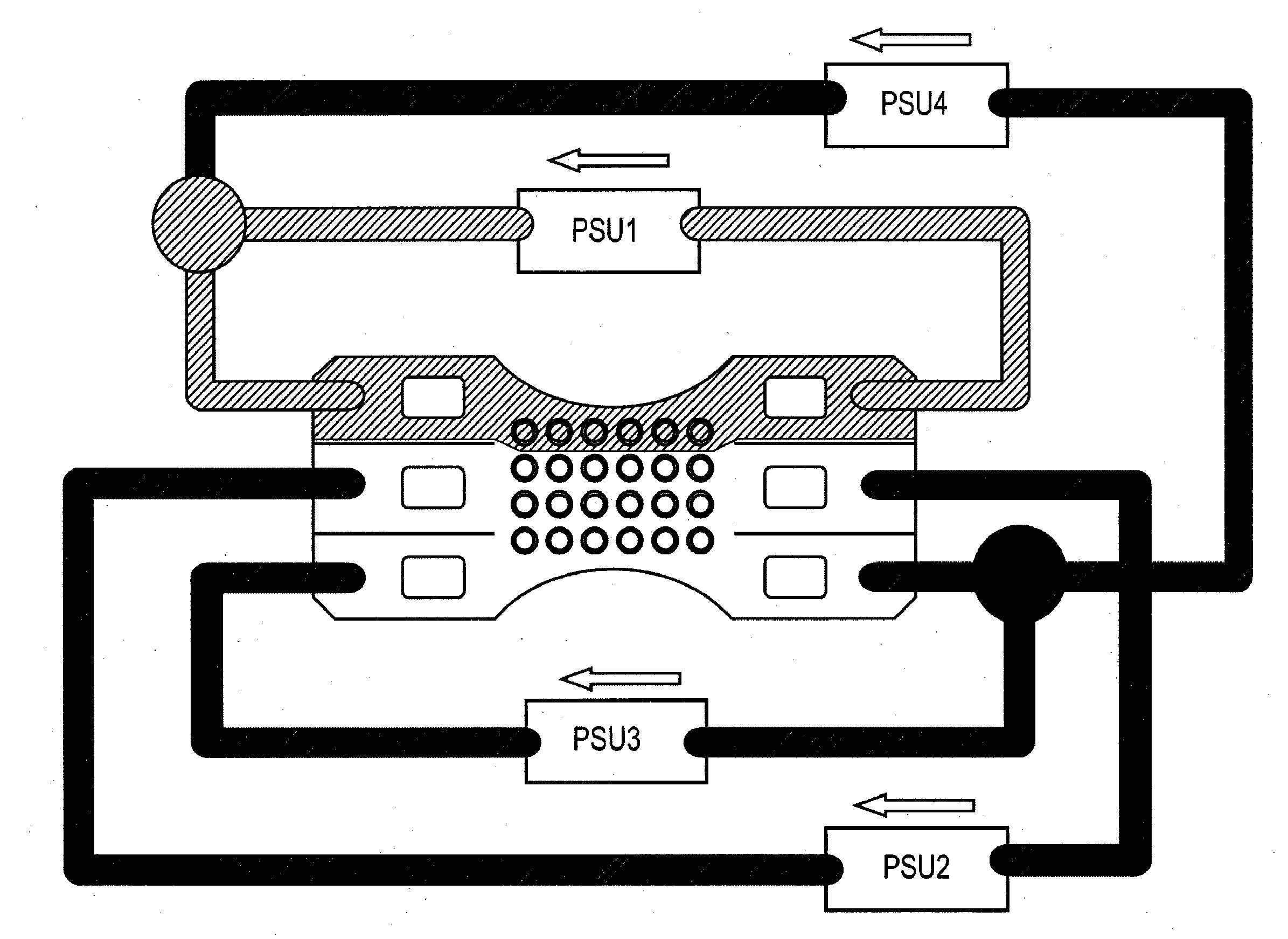
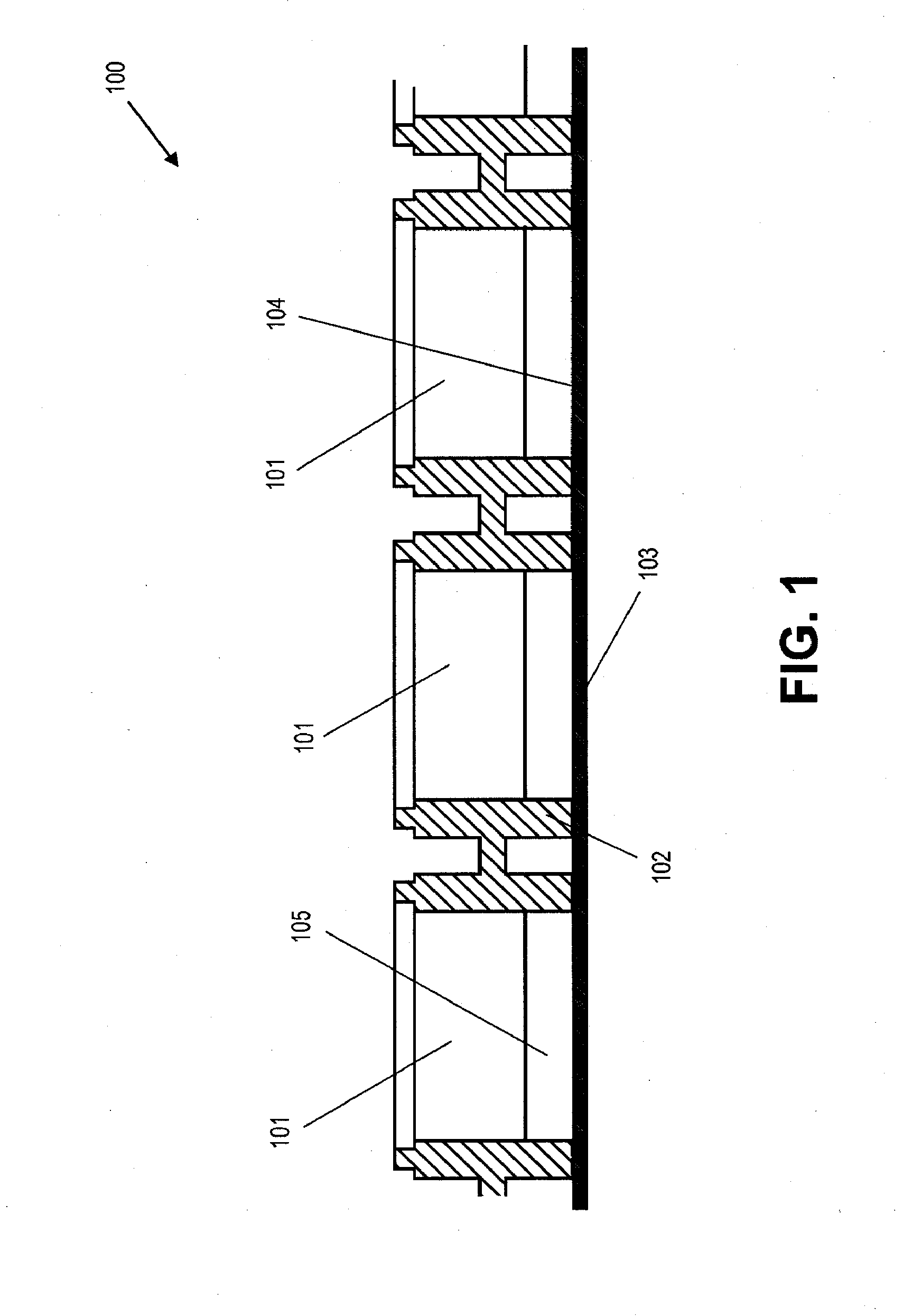
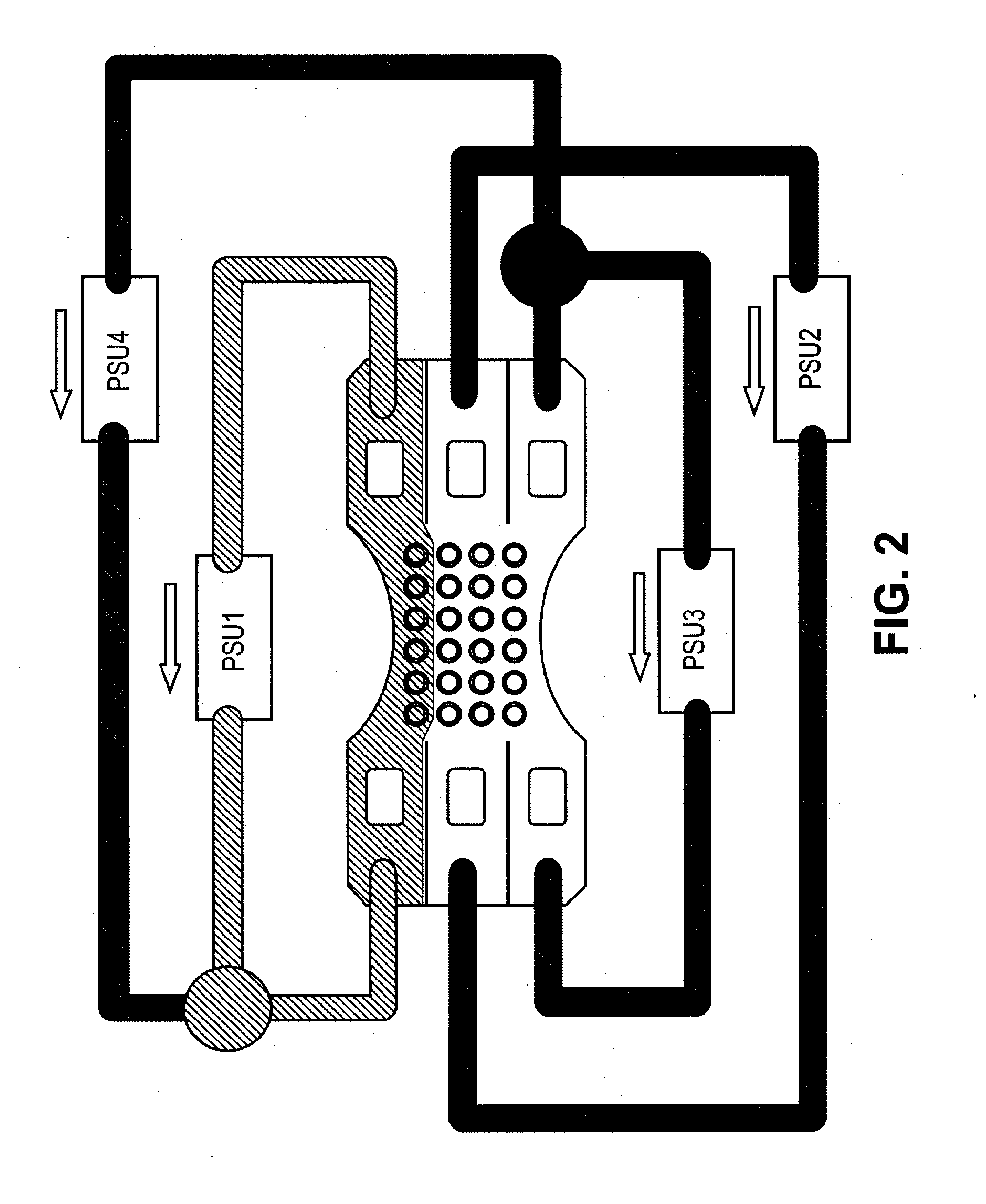
  • Methods and systems for fast PCR heating
  • Methods and systems for fast PCR heating
  • Methods and systems for fast PCR heating

Examples


example 1

Coated Metal Plate

[0126]Nominally 0.4 mm thick metal plates were produced from bulk processed material on a large scale where a metal ingot (e.g., 5 ton metal ingot) enters the process and is rolled and coated in a continuous operation. The material was an aluminum alloy rolled to a half-hard condition and then coated on one side (e.g., a top side) to a nominal thickness of about 10 microns with a polypropylene compatible material. This material allows polypropylene to be heat-sealed (or welded) to the metal plate, and does not inhibit the PCR. The other side (bottom) of the sheet was coated with an epoxy primer to a nominal thickness of 5 microns. This is present to normalize the infrared emissivity of the bottom side of the sheet. The material was slit into 160 mm wide strips and supplied in coiled form to an automatic stamping line where the individual plates are produced. The epoxy coating was then selectively removed from the contact fingers at the ends of the plates to allow e...

example 2

Polypropylene Moulding

[0127]To contain the liquid samples placed on the plate, a polypropylene moulding consisting of an array of vertical tube structures was welded to the metal plate of Example 1. The polypropylene moulding was formed of a plurality of tubes to define sample areas (or wells). The size and pattern of the tubes may be a matter of user choice; any pattern that fits within the actively temperature-controlled area in the middle of the plate may be used. Two familiar-looking options were selected: a 6×4 tube array on a 9 mm pitch, and an 8×12 array on a 4.5 mm pitch. The whole assembly weighed 10.5 g and was readily recyclable. Appropriately for a single-use item, the manufacturing cost of the consumable was low.

[0128]While certain microplates have been describes as being consumable ore recyclable, it will be appreciated that in some cases such microplates need not be consumable or recyclable. In some embodiments, such microplates may be reusable, non-consumable, or non...


PUM

PropertyMeasurementUnit
thicknessaaaaaaaaaa
thicknessaaaaaaaaaa
thicknessaaaaaaaaaa

Abstract

A microplate for polymerase chain reaction (PCR) comprises a substrate having a metallic material for heating PCR samples, and a barrier layer disposed adjacent to the substrate. In some cases, the barrier layer is formed of a first polymeric material. The microplate includes one or more wells for containing PCR samples. The one or more wells are formed of a second polymeric material sealed to the barrier layer. In some cases, the substrate can provide a PCR ramp rate of at least about 5° C. / second.

Description

CROSS-REFERENCE[0001]This application claims priority to U.S. Provisional Patent Application No. 61 / 424,551, filed Dec. 17, 2010 and U.S. Provisional Patent Application No. 61 / 545,063, filed Oct. 7, 2011, which applications are entirely incorporated herein by reference.BACKGROUND OF THE INVENTION[0002]In many fields specimen carriers in the form of support sheets, which may have a multiplicity of wells or impressed sample sites, are used for various processes where small samples are heated or thermally cycled. A particular example is the Polymerase Chain Reaction method (often referred to as PCR) for replicating DNA samples. Such samples require rapid and accurate thermal cycling, and are typically placed in a multi-well block and cycled between several selected temperatures in a pre-set repeated cycle. It is important that the temperature of the whole of the sheet or more particularly the temperature in each well be as uniform as possible.[0003]The samples may be liquid solutions, ...

Claims


Application Information

Patent Timeline
Patent Type & Authority Applications(United States)
IPC IPC(8): C12M1/40C12P19/34
CPCB01L3/50851B01L3/50853B01L7/52B01L2300/1827B01L2300/0829B01L2300/1822B01L7/54B01L3/5027B01L7/00C12Q1/6806B01L2300/1816B01L2300/16B01L2300/0887B01L2200/16B01L2200/10B01L2300/1811C12P19/34
Inventor GUNTER, IANLEWIS, RICHARD
Owner BJS IP LTD
Learn More