
Flexible channel for use on endoscope

a flexible channel and endoscope technology, applied in the field of flexible channels, to achieve the effect of maintaining positional stability, reducing the outside diameter of the flexible channel, and suitable flexibility in bending directions

Inactive Publication Date: 2014-03-04
FUJIFILM CORP
View PDF6 Cites 2 Cited by
  • Summary
  • Abstract
  • Description
  • Claims
  • Application Information

AI Technical Summary

Benefits of technology

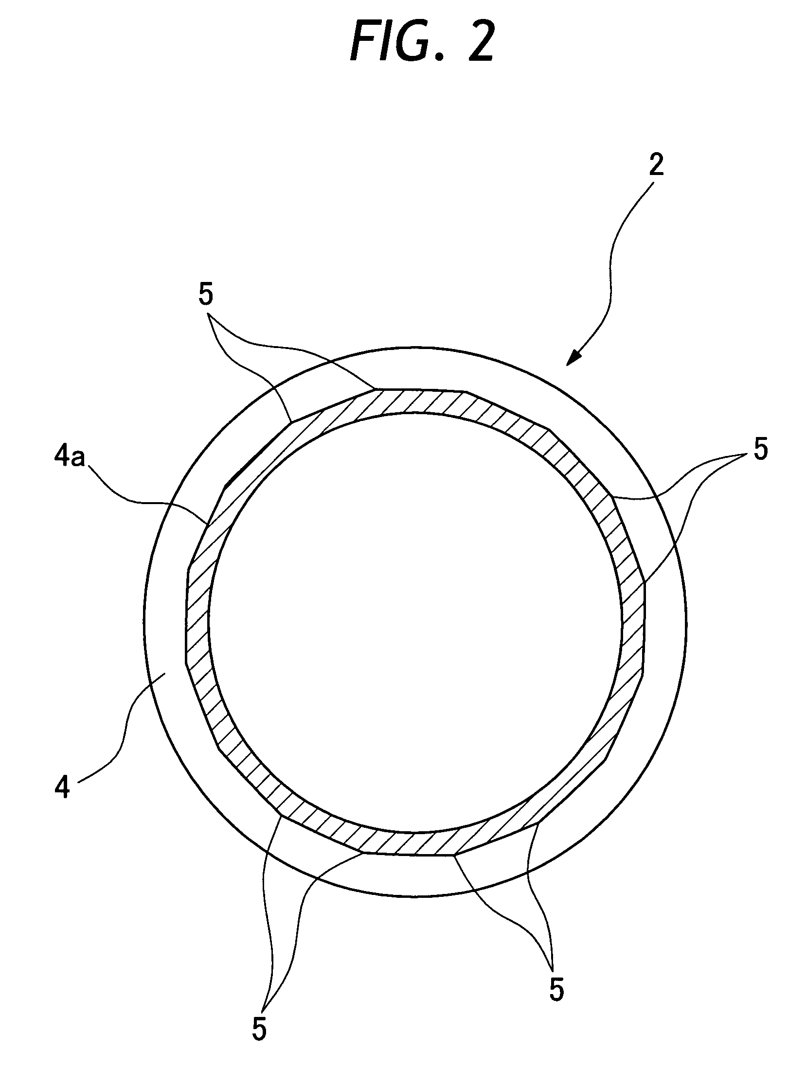
[0009]It is another object of the present invention to provide a flexible channel which is so arranged as to let a reinforcing coil in a helical groove on the outer periphery of a flexible tube positively bite on root portions of the helical groove and stay in position within the helical groove in a stabilized state free of positional deviations relative to the flexible tube.
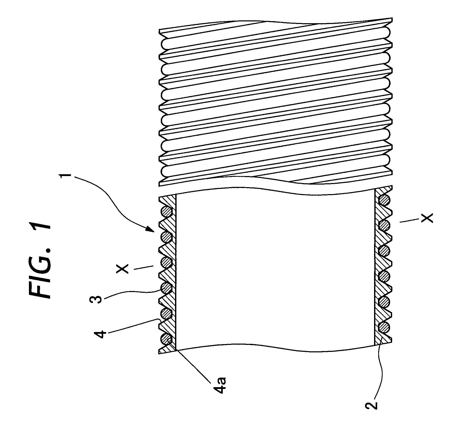
[0013]The reinforcing coil should have an inside diameter smaller than the maximum root diameter of the helical groove. That is to say, the inside diameter of the reinforcing coil should not exceed the maximum root diameter of the helical groove. If the inside diameter of the reinforcing coil exceeds the maximum root diameter, it will become difficult for the coil to press root portions of the groove strong enough for maintaining positional stability. On the other hand, in case the inside diameter of the reinforcing coil is smaller than the minimum root diameter, obstructive protrusions and bumps may appear on the inner periphery of the flexible tube. Therefore, it is preferable that the inside diameter of the reinforcing coils be approximately equivalent to or slightly larger than the minimum root diameter and smaller than the maximum root diameter of the helical groove. By making arrangements in this way, it becomes possible to let the reinforcing coil bite firmly on root portions of the helical groove and stay in position in a stabilized state even when a twisting force is applied to the endoscopic biopsy channel.
[0014]Preferably, the reinforcing coil is formed of a spring metal wire, and wound in a relatively wide pitch rather than a tight and narrow pitch from the standpoint of securing suitable flexibility in bending directions and downsizing the outside diameter of the flexible channel. However, from the standpoint of shape retainability of the flexible channel, the pitch of the coil should not be widened to an excessive degree.

Problems solved by technology

A reinforcing coil in a helical groove around a flexible tube of the biopsy channel is not securely fixed in the groove, so that application of a twisting force may cause positional deviations to the reinforcing coil in the groove, leaving the coil in an instable state.
However, since root portions of the helical groove on the flexible tube is very small in wall thickness, so that inward deformations may occur to these portions under the pressing force exerted by the reinforcing coil, forming inward protrusions on the inner periphery of the flexible tube to such a degree as to hinder insertion of forceps or other medical treating instruments.

Method used


Image

  • Flexible channel for use on endoscope
  • Flexible channel for use on endoscope
  • Flexible channel for use on endoscope

Examples


Embodiment Construction

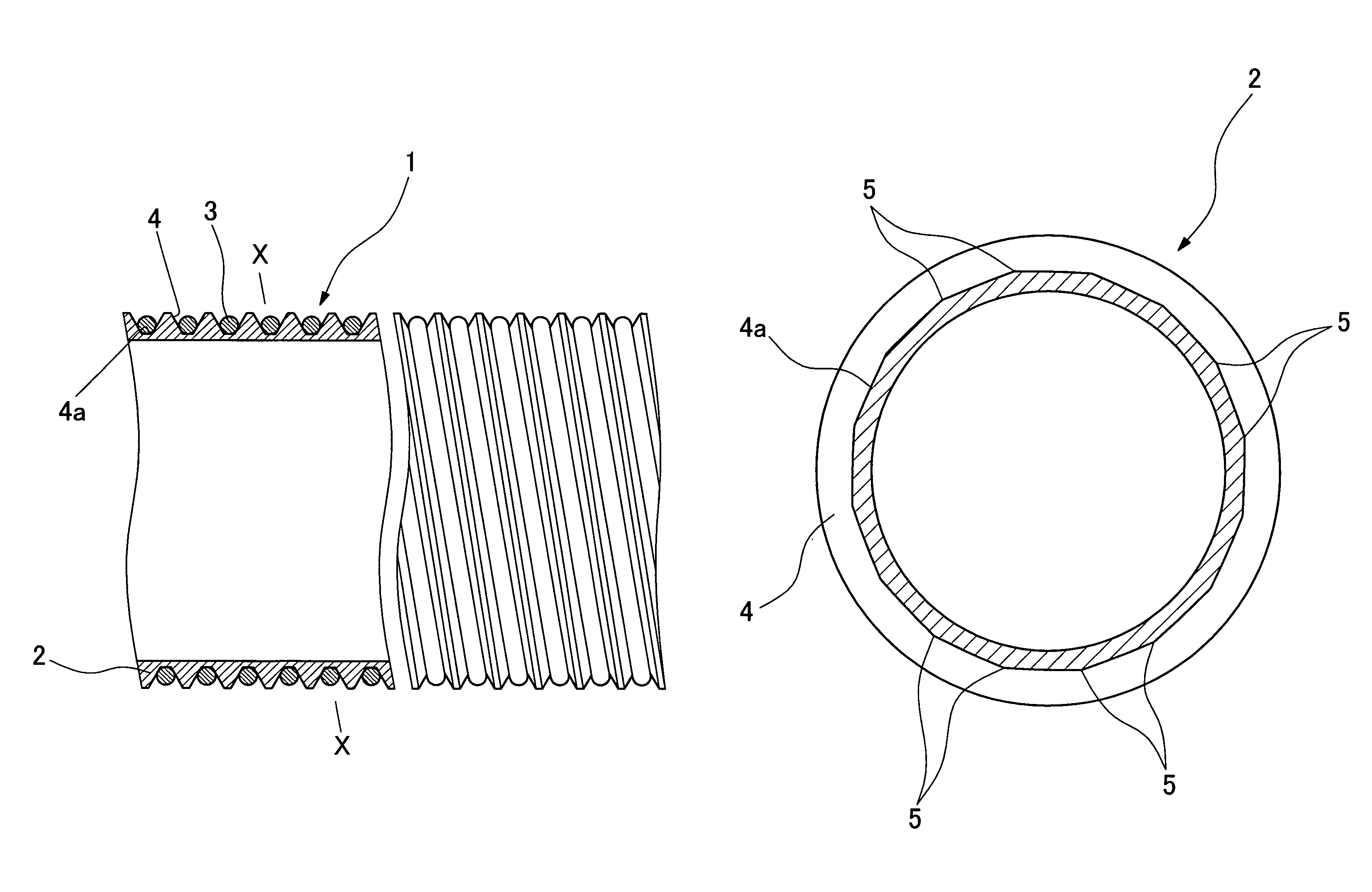
[0025]Hereafter, the present invention is described more particularly by way of its preferred embodiments. Shown in FIG. 1 is a fragmentary sectional view of a flexible channel according to the present invention. In this case, the flexible channel is extended from a manipulating head assembly to a fore distal end of an insertion portion of an endoscope to serve as the so-called biopsy channel for insertion of forceps or other medical treating instruments. However, it is to be understood that application of the flexible channel is not limited to a biopsy channel. For example, the flexible channel can be incorporated into an endoscopic insertion portion to provide a passage which is flexible in bending directions and which has satisfactory shape retainability, for example, to serve as a fluid supply passage or as a sheath of control cables.

[0026]As shown in the drawing, the flexible channel 1 is composed of a flexible tube 2 and a reinforcing coil 3. The flexible tube 2 is formed of a...


PUM


Abstract

A flexible channel to be incorporated into an endoscopic insertion portion having a flexible portion at least in part of its length, for the purpose of providing a flexible passage internally of the endoscopic insertion portion. The flexible channel is composed of a flexible tube with a helical groove on and around its outer periphery, and a reinforcing coil fitted in the helical groove on the flexible tube. At the root of the helical groove, angular projections are formed at intervals in the longitudinal direction and the reinforcing coil is tightly pressed tightly against the angular projections.

Description

[0001]This invention claims foreign priority to Japanese Patent Application No. 2006-154194 filed Jun. 2, 2006.BACKGROUND OF THE INVENTION[0002]1. Field of the Art[0003]This invention relates to a flexible channel to be fitted in an endoscopic insertion portion to serve as a passage of forceps or other surgical or medical instruments, for insertion of operating wires or other components, or as a passage for sending a fluid into or out of a body cavity.[0004]2. Prior Art[0005]Generally, the so-called biopsy channel is provided in an endoscopic insertion portion for introduction of forceps or other treating instruments into a body cavity. The biopsy channel of this sort is extended forward from an manipulating head assembly as far as a fore distal end of an elongated insertion portion. In case the endoscopic insertion portion has a flexible section in part of its length, the biopsy channel needs to have a flexible structure in that section. Therefore, usually a biopsy channel is forme...

Claims


Application Information

Patent Timeline
Patent Type & Authority Patents(United States)
IPC IPC(8): A61B1/04A61M25/00
CPCG02B23/2476A61B1/005A61B1/018A61B1/0011
Inventor OGURA, AKIRAWATANABE, JOJI
Owner FUJIFILM CORP
Learn More