
Nozzle ring machining clamp for turbocharger

A turbocharger and nozzle ring technology, which is applied to manufacturing tools, workpiece clamping devices, etc., can solve the problems of nozzle ring variation, insufficient stability, and the influence of nozzle ring processing operations, and achieve the effect of maintaining a stable degree of positioning.

Active Publication Date: 2021-09-03
抚州发那特机械科技有限公司
View PDF6 Cites 0 Cited by
  • Summary
  • Abstract
  • Description
  • Claims
  • Application Information

AI Technical Summary

Problems solved by technology

[0003] The nozzle ring is a stainless steel product. The clamping operation of the nozzle ring in the prior art generally includes an upper mold and a lower mold installed together. The inside of the upper mold and the lower mold is a hollow structure, so that the nozzle ring is clamped sideways. Fixed operation; however, there are certain defects in the existing technology. The single contradictory clamping of the nozzle ring from the side wing is not only insufficient in stability, but also easily causes the problem of nozzle ring deformation; if it is clamped on the annular surface of the nozzle ring, It will affect the processing operation of the nozzle ring

Method used


Image

  • Nozzle ring machining clamp for turbocharger
  • Nozzle ring machining clamp for turbocharger
  • Nozzle ring machining clamp for turbocharger

Examples


Embodiment Construction

[0027] The technical solutions in the embodiments of the present invention will be clearly and completely described below in conjunction with the accompanying drawings in the embodiments of the present invention, examples of which are shown in the accompanying drawings. When the following description refers to the accompanying drawings, the same numerals in different drawings refer to the same or like elements unless otherwise indicated.

[0028] Apparently, the described embodiments are only some of the embodiments of the present invention, but not all of them. Based on the embodiments of the present invention, all other embodiments obtained by persons of ordinary skill in the art without making creative efforts belong to the protection scope of the present invention.

[0029] The specific implementation of the present invention will be described in detail below in conjunction with specific embodiments.

[0030] In one embodiment;

[0031] see figure 1 and figure 2 , pro...


PUM


Abstract

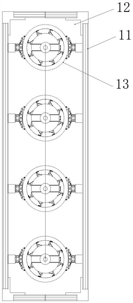
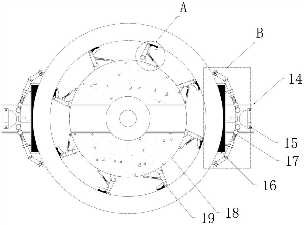
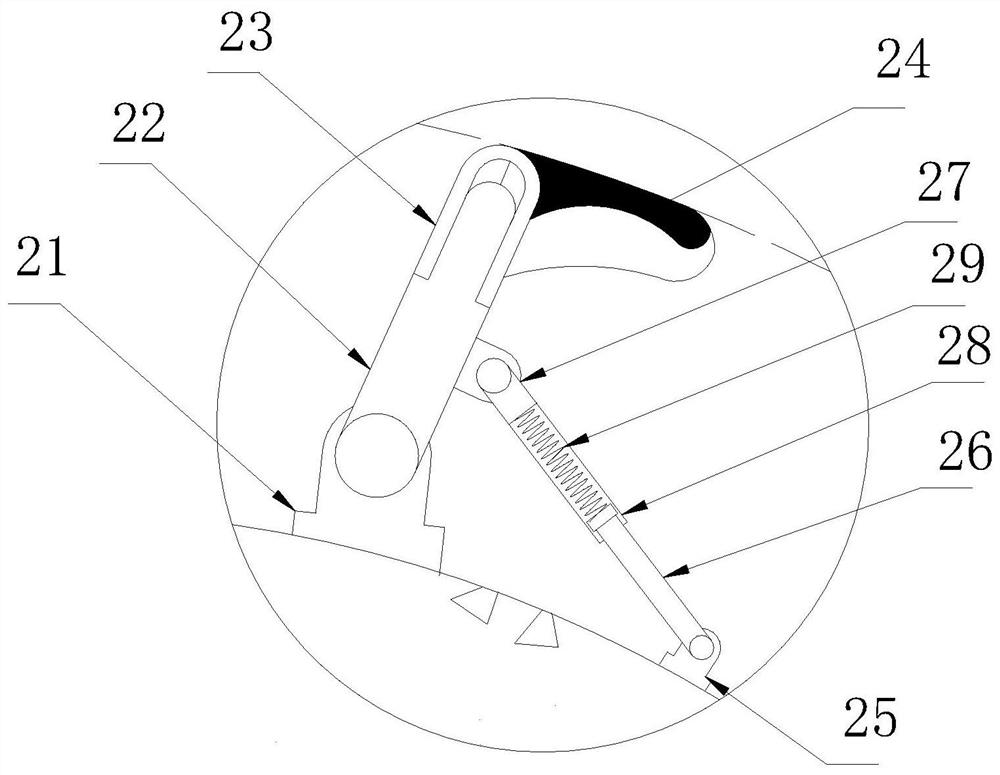
The invention relates to the technical field of nozzle ring machining, in particular to a nozzle ring machining clamp for a turbocharger. The nozzle ring machining clamp for the turbocharger comprises a loading rack, an operation carrying surface arranged on the loading rack, and a plurality of clamp mechanisms mounted on the operation carrying surface; each clamp mechanism is provided with a transmission module, an inner positioning assembly and an outer positioning assembly, wherein the inner positioning assemblies and the outer positioning assemblies are installed on the transmission modules; the inner positioning assembly comprises a built-in rotating disc and an inner extrusion piece installed on the outer edge of the built-in rotating disc; the inner extrusion piece extrudes and is attached to the inner ring surface of the nozzle ring; the outer positioning assembly comprises a displacement seat, an outer clamp assembly and an outer limiting assembly, wherein the outer clamp assembly and the outer limiting assembly are installed on the displacement seat; the displacement seat is installed on the track of the transmission module; the inner side of the outer clamp assembly is attached to the outer ring surface of the nozzle ring; and the two ends of the outer limiting assembly are attached to the outer ring surface of the nozzle ring in a rolling type tangential mode. According to the design, multi-point annular support is formed on the inner ring surface of the nozzle ring; and the outer clamp assembly is adopted on the outer ring surface of the nozzle ring to clamp the two sides of the nozzle ring.

Description

technical field [0001] The invention relates to the technical field of nozzle ring processing, in particular to a nozzle ring processing fixture for a turbocharger. Background technique [0002] The nozzle ring is a very important part of the turbocharger. Its function is to control the amount of exhaust gas entering the box in the volute. When the engine speed increases, the amount of exhaust gas reaches a certain level, and gradually prevents the exhaust gas from entering the "bypass." ”; so that part of the exhaust gas directly enters the exhaust pipe through the pressure relief valve hole without pushing the turbine, so that the turbocharger can be kept in normal working condition. [0003] The nozzle ring is a stainless steel product. The clamping operation of the nozzle ring in the prior art generally includes an upper mold and a lower mold installed together. The upper mold and the lower mold are hollow structures inside, so that the nozzle ring is clamped sideways. ...

Claims


Application Information

Patent Timeline
Patent Type & Authority Applications(China)
IPC IPC(8): B25B11/00
CPCB25B11/00
Inventor 高欢李露王子亚权乐
Owner 抚州发那特机械科技有限公司
Learn More