
Super-junction trench MOSFET with multiple trenched source-body contacts

a technology of source-body contacts and super-junction trenches, which is applied in the direction of semiconductor devices, electrical equipment, basic electric elements, etc., can solve the problems of increased cost not conductive to mass production, unstable manufacturing yield, and dangerous condition of charges imbalance, so as to minimize the influence of charges imbalance, improve performance optimization and manufacturing capability, and improve cost-effective

Active Publication Date: 2014-02-11
FORCE MOS TECH CO LTD
View PDF1 Cites 0 Cited by
  • Summary
  • Abstract
  • Description
  • Claims
  • Application Information

AI Technical Summary

Benefits of technology

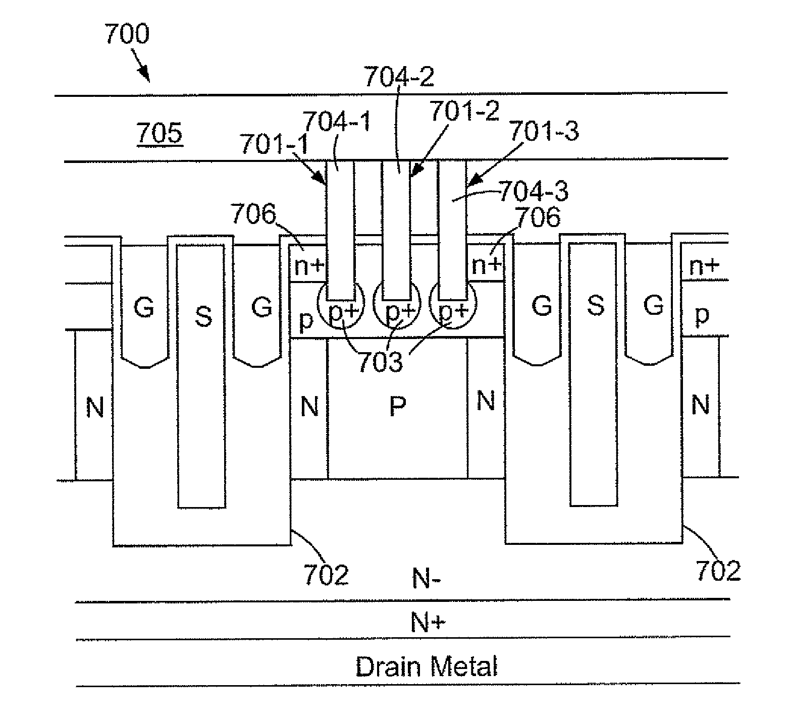
[0009]The present invention provides a super-junction trench MOSFET with resurf stepped oxides (RSO) having additional freedom for better performance optimization and manufacturing capability by tuning a thick oxide thickness to minimize influence of the charges imbalance, trapped charges, etc. Therefore, the present invention only requires one kind gate trenches and a single epitaxial layer to achieve a better cost effective than the prior arts. Moreover, the present invention also provides multiple trenched source-body contacts in a mesa between two adjacent gate trenches in an active area because that, for middle voltage device (100˜200V) with narrow mesa, a single trenched source-body contact with a narrow contact CD (Critical Dimension) disposed in unit cell is enough for source-body contact, however, for high voltage device (above 200V) with wide mesa, multiple trenched source-body contacts with narrow contact CDs are required. According to the present invention, the multiple trenched source-body contacts are formed in unit cell and filled with tungsten plugs for wide mesa, furthermore, source regions are only formed along channel regions near the gate trenches, not between adjacent trenched source-body contacts for UIS (Unclamped Inductance Switching) current enhancement.

Problems solved by technology

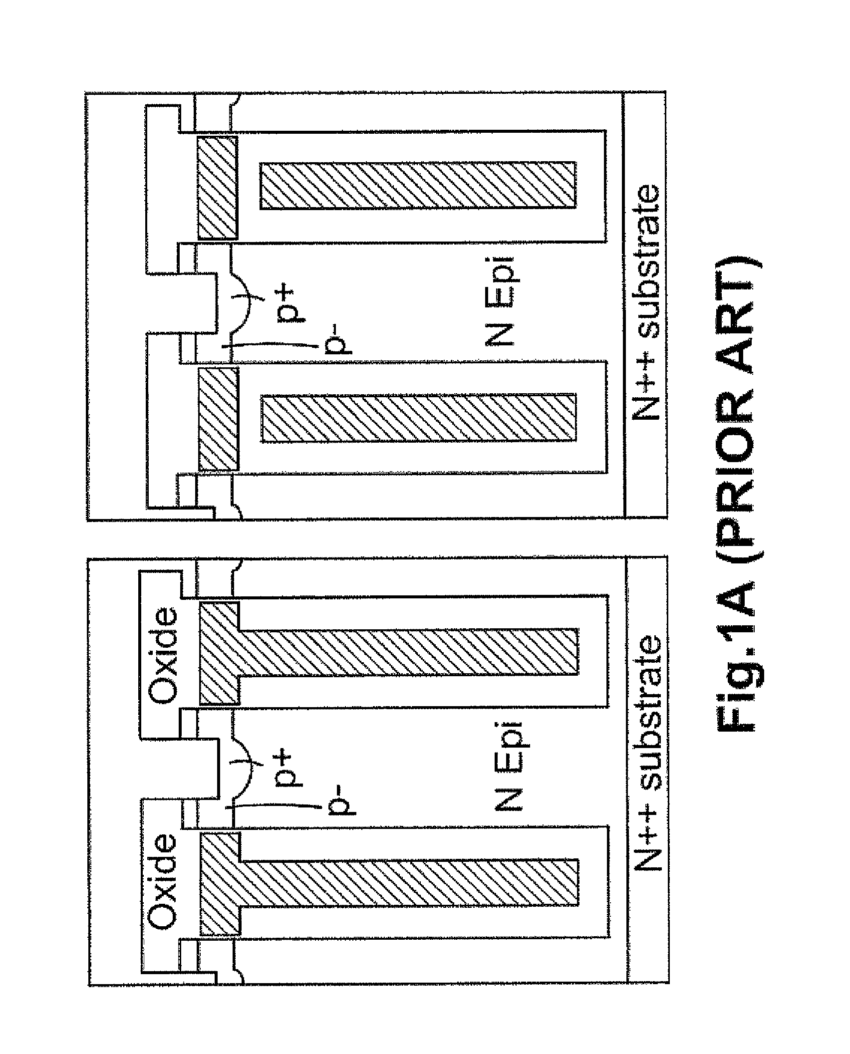
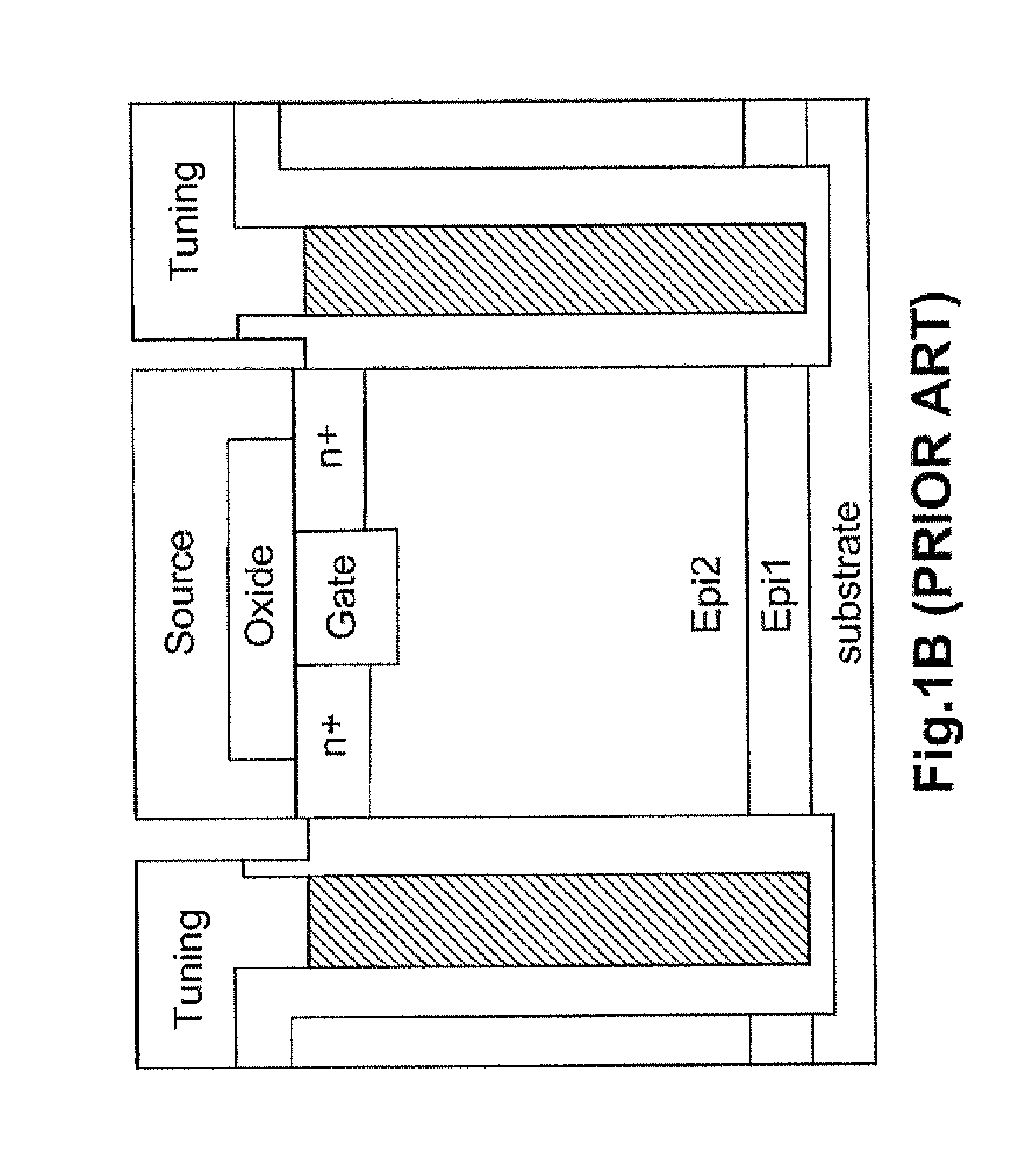
As is known to all, a super-junction trench MOSFET is implemented by a p type column structure and an n type column structure arranged in parallel and connecting to each other onto a heavily doped substrate, however, the manufacturing yield is not stable because the super-junction trench MOSFET is very sensitive to the fabrication processes and conditions such as: the p type column structure and the n type column structure dopant re-diffusion issue induced by subsequent thermal processes; trapped charges within the column structure, etc.
. . . . All that will cause a hazardous condition of charges imbalance to the super-junction trench MOSFET.
However, the disclosed method of this prior art is not effective because that, firstly, the p type column structure is formed by growing an additional p type epitaxial layer in deep trenches etched in an n type epitaxial layer; secondly, an additional CMP (Chemical Mechanical Polishing) is required for surface planarization after the p type epitaxial layer is grown; thirdly, double trench etches are necessary (one for shallow trenches for trenched gates formation and another for the deep trenches for the p type column structure formation), all the increased cost is not conductive to mass production.
Moreover, other factors such as: the charges imbalance caused by the trapped charges within the column structure is still not resolved.

Method used


Image

  • Super-junction trench MOSFET with multiple trenched source-body contacts
  • Super-junction trench MOSFET with multiple trenched source-body contacts
  • Super-junction trench MOSFET with multiple trenched source-body contacts

Examples


Embodiment Construction

[0033]In the following Detailed Description, reference is made to the accompanying drawings, which forms a part thereof, and in which is shown by way of illustration specific embodiments in which the invention may be practiced. In this regard, directional terminology, such as “top”, “bottom”, “front”, “back”, etc., is used with reference to the orientation of the Figure(s) being described. Because components of embodiments can be positioned in a number of different orientations, the directional terminology is used for purpose of illustration and is in no way limiting. It is to be understood that other embodiments may be utilized and structural or logical changes may be make without departing from the scope of the present invention. The following detailed description, therefore, is not to be taken in a limiting sense, and the scope of the present invention is defined by the appended claims. It is to be understood that the features of the various exemplary embodiments described herein...


PUM


Abstract

A super-junction trench MOSFET with split gate electrodes is disclosed for high voltage device by applying multiple trenched source-body contacts with narrow CDs in unit cell. Furthermore, source regions are only formed along channel regions near the gate trenches, not between adjacent trenched source-body contacts for UIS (Unclamped Inductance Switching) current enhancement.

Description

CROSS-REFERENCE TO RELATED APPLICATION[0001]This application is a Continuation-In-Part of U.S. patent application Ser. No. 13 / 303,474 of the same inventor, filed on Nov. 23, 2011 now U.S. Pat. No. 8,373,255 entitled “Super-Junction Trench MOSFET with RESURF stepped oxides and split gate electrodes”, which is a Continuation-In-Part of U.S. patent application Ser. No. 12 / 654,637 filed Dec. 28, 2009, now U.S. Pat. No. 8,067,800 of the same inventor.FIELD OF THE INVENTION[0002]This invention relates generally to the cell structure, device configuration and fabrication process of power semiconductor devices. More particularly, this invention relates to a novel and improved cell structure, device configuration and improved fabrication process of a super-junction trench MOSFET (Metal Oxide Semiconductor Field Effect Transistor) with multiple trenched source-body contacts.BACKGROUND OF THE INVENTION[0003]Compared to the conventional trench MOSFETs, super-junction trench MOSFETs are more att...

Claims


Application Information

Patent Timeline
Patent Type & Authority Patents(United States)
IPC IPC(8): H01L29/78
CPCH01L29/42376H01L29/7811H01L29/1095H01L29/407H01L29/0634H01L29/7813H01L29/456H01L29/0619H01L29/42368H01L29/41766H01L29/4236
Inventor HSIEH, FU-YUAN
Owner FORCE MOS TECH CO LTD
Learn More