
LED light bulb providing high heat dissipation efficiency

a technology of led light bulbs and heat dissipation efficiency, which is applied in the direction of lighting and heating apparatus, lighting support devices with built-in power, and with built-in power. it can solve the problems of poor heat dissipation efficiency of leds. achieve the effect of high heat dissipation efficiency

Inactive Publication Date: 2014-02-04
HSU WEI LIN
View PDF15 Cites 86 Cited by
  • Summary
  • Abstract
  • Description
  • Claims
  • Application Information

AI Technical Summary

Benefits of technology

The invention aims to address the concerns of LED light bulbs regarding current leakage and heat dissipation. The design includes a power receiving base that fully encases the heat sink without exposing it, reducing the risk of electric shock to users. Additionally, the light source baseboard is composed of aluminum, which allows for the mounting of light emitting elements on both sides to prevent the waste heat from concentrating on one surface. These technical effects result in improved safety and efficient heat dissipation.

Problems solved by technology

However, the luminosity provided by a single LED is still inadequate.
As a result, the substrate holding the LEDs accumulates a great amount of waste heat.
If the waste heat cannot be dissipated efficiently from the substrate to the outside, high temperature affects lighting efficiency of the LEDs, and the lifespan of the LEDs suffers.
However, it also has a drawback, i.e. coupling with the lamp shell is accomplished via the heat sink rather then the power receiving base.
As the LED light bulb has to pass a severe high voltage applying test under an external voltage of 4000 volts, electric power could pass through the protrusive ring and break through insulation of the insulator to damage the conversion circuit in the heat sink and make the LED light bulb fail to pass the safety regulation test.
The LED light bulb thus formed has the concern of current leakage through the heat sink when in use.
As a result, a greater amount of waste heat is generated and creates a concern of damaging the LEDs.

Method used


Image

  • LED light bulb providing high heat dissipation efficiency
  • LED light bulb providing high heat dissipation efficiency
  • LED light bulb providing high heat dissipation efficiency

Examples


Embodiment Construction

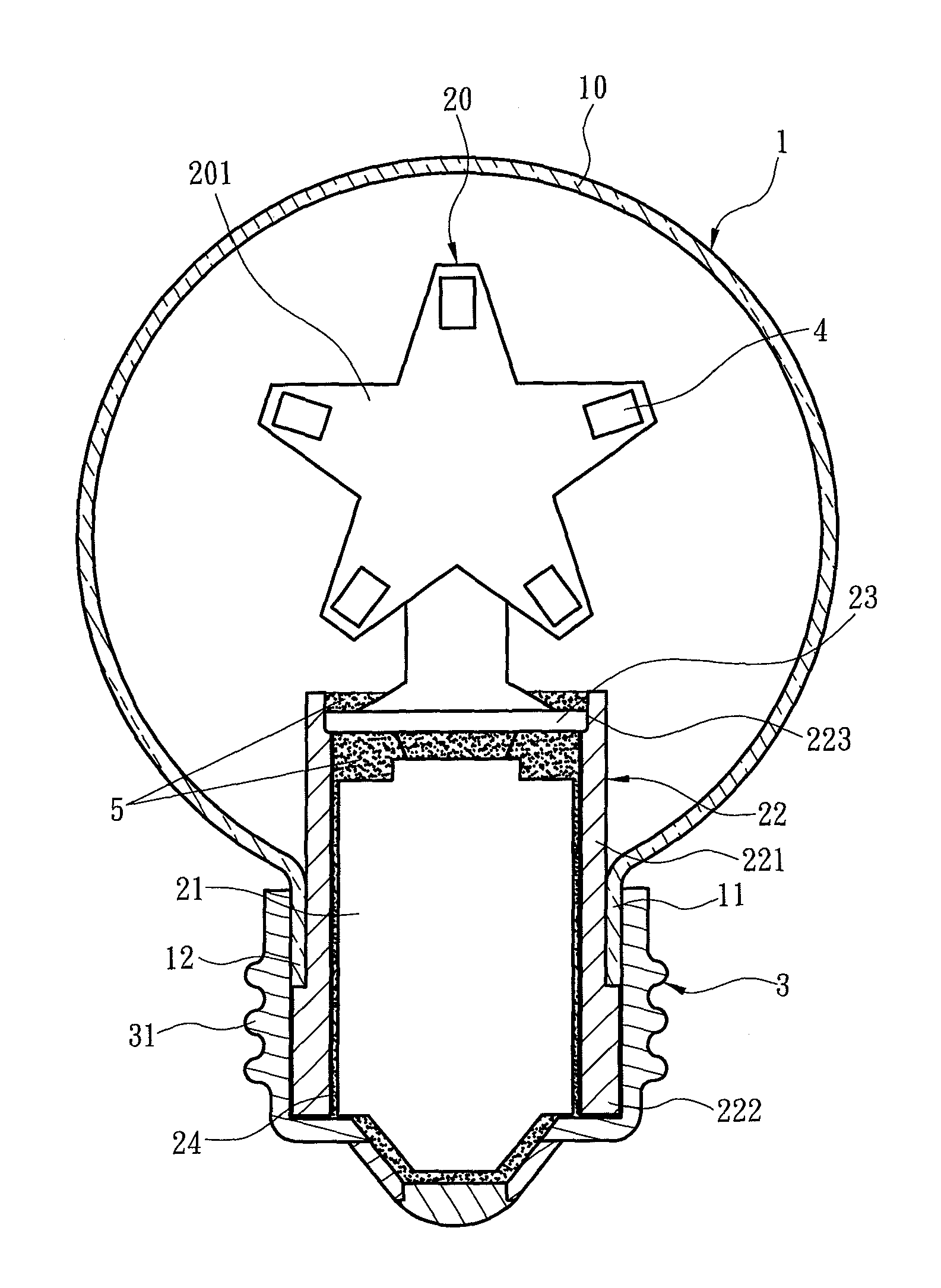
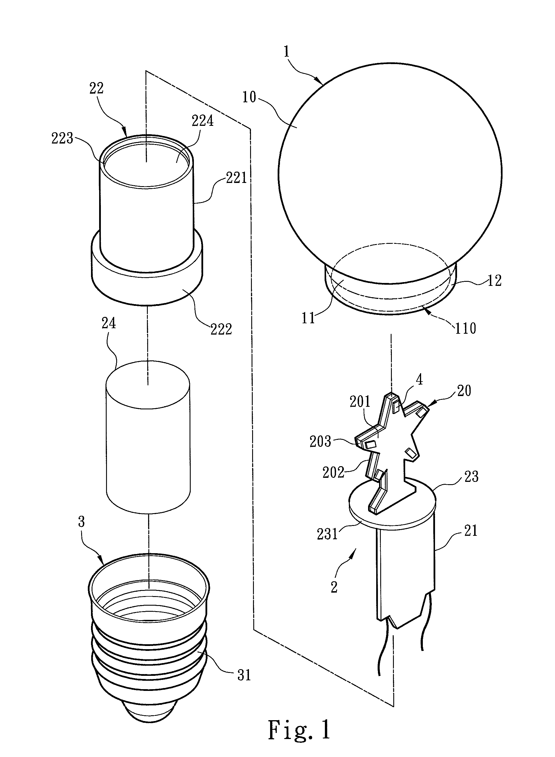
[0027]The present invention aims to propose an LED light bulb providing high heat dissipation efficiency. Please referring to FIG. 1, the LED light bulb includes a lamp shell 1, a light emitting assembly 2, a heat sink 22, an insulation bushing 24 and a power receiving base 3. The lamp shell 1 includes a light transmissive portion 10 and a holding portion 11 located below and connected to the light transmissive portion 10. The light transmissive portion 10 forms a space to hold the light emitting assembly 2. The holding portion 11 has an opening 110 and extended to form a retaining section 12.

[0028]The light emitting assembly 2 includes at least one light source baseboard 20 located in the light transmissive portion 10 and a circuit board 21 electrically connecting to the light source baseboard 20. The light source baseboard 20 has at least one light emitting element 4 mounted thereon. In this embodiment the light emitting element 4 is a light emitting diode. The light source basebo...


PUM


Abstract

An LED light bulb includes a lamp shell, a light emitting assembly and a power receiving base. The lamp shell includes a light transmissive portion and a holding portion. The light emitting assembly includes a light source baseboard located in the light transmissive portion and a circuit board connecting to the light source baseboard. The circuit board is surrounded by a heat sink. The heat sink includes a heat collecting section and a holding section extended from the heat collecting section into the power receiving base such that the power receiving base fully encases the heat sink without exposing. The inner surface of the power receiving base connects to the outer surface of the holding section so that heat generated by the light source baseboard is absorbed by the heat collecting section and transmitted via the holding section to the power receiving base for dissipating.

Description

FIELD OF THE INVENTION[0001]The present invention relates to an LED light bulb and particularly to an LED light bulb providing high heat dissipation efficiency.BACKGROUND OF THE INVENTION[0002]Light emitting diode (LED) provides many advantages over the traditional tungsten light bulb, such as longer lifespan, lower power consumption, higher luminosity and less fabrication materials. These days as energy saving and carbon reduction are growing concerns in the mind of many people, LED has been widely used. Apart from adopted on traffic lights or signal lights on electric appliances, it also gets growing acceptance in general houses. Techniques to couple the LED with the conventional light bulb have been proposed in prior art. For instance, R.O.C. patent No. I293807 entitled “LED light bulb equipped with a constant current circuit” discloses an LED light bulb which includes a lamp cap, a lamp shell, a plurality of LEDs coupled in series and a step-down constant current circuit. The la...

Claims


Application Information

Patent Timeline
Patent Type & Authority Patents(United States)
IPC IPC(8): F21V29/00F21S9/00F21V17/00
CPCF21W2121/00F21V3/00F21V29/713F21Y2105/10F21K9/232F21Y2115/10F21Y2107/90
Inventor CHUANG, SHENG-YI
Owner HSU WEI LIN
Learn More