
Method and apparatus for computer-aided tissue engineering for modeling, design and freeform fabrication of tissue scaffolds, constructs, and devices

a computer-aided tissue and engineering technology, applied in the field of method and apparatus for computer-aided tissue engineering for modeling, design and freeform fabrication of tissue scaffolds, constructs, devices, etc., can solve the problems of difficult creation of heterogeneous cellular structures, inability to achieve the complexity level of an organ using standard techniques, and limited techniques in their level of sophistication

Active Publication Date: 2014-01-28
DREXEL UNIV
View PDF15 Cites 55 Cited by
  • Summary
  • Abstract
  • Description
  • Claims
  • Application Information

AI Technical Summary

Benefits of technology

The present invention relates to a system for creating devices that combine biological and artificial elements. It is designed to deposit biopolymer solutions and living cells on scaffolds to create complex tissue structures with precise cell placement and control over growth factors and other bioactive compounds. The system can also form larger and thicker tissue structures with complex layouts, such as vascular networks.

Problems solved by technology

These techniques are very limited in their level of sophistication.
Organized, heterogeneous cellular structures are very difficult to create, and impossible to create at the complexity level of an organ using standard techniques.
Seeding these kinds of scaffolds may not be enough to stimulate the cells into responding in the desired manner.
Unfortunately, many Solid Freeform Fabrication (SFF) techniques are not biologically friendly using techniques that cannot handle a wide range of wet materials, gels or solutions.
Also, many SFF techniques utilize harsh solvents, high temperatures, high pressures, and other factors that are not conducive to biological systems.
Many SFF techniques, such as stereolithography, fused deposition methods, and powder / binder-based techniques, are capable of creating tissue scaffolds, but cannot directly deposit cells or biological factors into the scaffold.
This process was designed for the purpose of constructing bone implants, not to provide a flexible process of creating various types of organs or biologically / chemically integrated systems and thus has several disadvantages with respect to construction of tissue engineering devices.
For example, the method is limited in materials since soft, gel-like materials cannot be used as scaffold layers.
This is a problem since many biological parts are soft or wet.
Thus, it is difficult to have two or more different materials within the same layer level.
Accuracy and recalibration is an issue as well since the scaffold layers are moved from station to station.
Thus, although a simple scaffold can be created by this method, a complex scaffold with controlled concentration gradients is difficult, if not impossible, to create.
This is a serious disadvantage since cells are very responsive to even the slightest differences in concentration gradients.
This is not a very practical system for depositing multiple, heterogeneous materials such as different types of cells and growth factors all within the same scaffold layer.
Further, it is difficult to take a multiple part assembly of STL files and print out a complex, biologically designed scaffold utilizing this method.
Thus, there are limitations in this method with respect to the CAD integration aspect as well.
This system also uses a single nozzle and does not incorporate CAD, thus being limited to simple designs written in Microsoft Qbasic.
This system is not capable of creating heterogeneous designs within a single layer.
Thus, this system is sufficient for creating basic scaffolds, but falls short of being able to create intricate scaffolds containing both biomimetic and non-biomimetic features.
This system utilizes a single-nozzle deposition system which has fine resolution, but is limited because of the glass capillary used for deposition.
The glass capillary limits the range of viscosities that are usable due to pressure limits, and also limits the types of solutions and suspensions that can be deposited due to clogging.
Also, the single nozzle system makes multi-material, heterogeneous deposition difficult.
It is unclear whether this system can be utilized to produce multi-part, heterogeneous STL files.
This single nozzle process also makes constructing complex parts very difficult, and limits the diverse range of materials available for deposition.
In addition, there are serious limitations with their disclosed multi-nozzle system which uses the same type of syringe thus limiting the types of materials that can be deposited.
In order to build good 3-dimensional structures, relatively viscous solutions are required, which means high pressure.
High pressure, however, may not be compatible with cells.
High pressure systems handling viscous materials have the problem of not being able to deposit fine structures with fine concentration gradients.
Finally, there is a flaw in the process described in this reference because they do not consider the fact that CAD programs do not have heterogeneous material capabilities.
Thus, they neglect a non-trivial and difficult step by assuming that they can create a multi-material part in CAD and print it out using multiple nozzles, which is not necessarily the case.
The reason for this is that the method described is not biologically friendly to cells.
Further, the inkjet printing method described by Vacanti creates problems for cellular deposition unless significant steps are taken to protect cells from shear stresses that would tear the cell apart.
The method used is primarily oriented towards building hard, bone-type scaffold structures and creation of soft, gel-like scaffolds using this method may be difficult.
Further heterogeneous capabilities are limited to materials that can be added on top of the layer, but not within the layer itself.
Means for affixing the layers such as barbs, or other mechanical affixing means is a disadvantage that may result in later complications due to wear, bone remodeling, or incompatibilities in material properties.
The method described by Weiss et al. thus lacks versatility and flexibility.
In addition, the majority of the SFF methods described are not biologically friendly for direct cell deposition.
For example, stereo-lithography, selective laser sintering, and fused deposition modeling cannot directly deposit cells due to heating and toxicity issues which will kill cells.
Ballistic particle manufacturing also has problems due to shear stresses that can damage cells, which are very sensitive and require low pressure or a protective method to reduce the shear stresses experienced by the cell.
The described 3DP method is also unable to directly seed cells into the interior of the part that is being constructed.
Thus, cells cannot be directly printed at specific locations inside the part.
This is a serious disadvantage when trying to create reproducibility between histotypic or organ culture samples.
Finer features require additional post-processing, such as salt-leaching, which again makes direct cellular deposition impossible.
However, there is no demonstration of use in this application.

Method used


Image

  • Method and apparatus for computer-aided tissue engineering for modeling, design and freeform fabrication of tissue scaffolds, constructs, and devices
  • Method and apparatus for computer-aided tissue engineering for modeling, design and freeform fabrication of tissue scaffolds, constructs, and devices
  • Method and apparatus for computer-aided tissue engineering for modeling, design and freeform fabrication of tissue scaffolds, constructs, and devices

Examples


examples

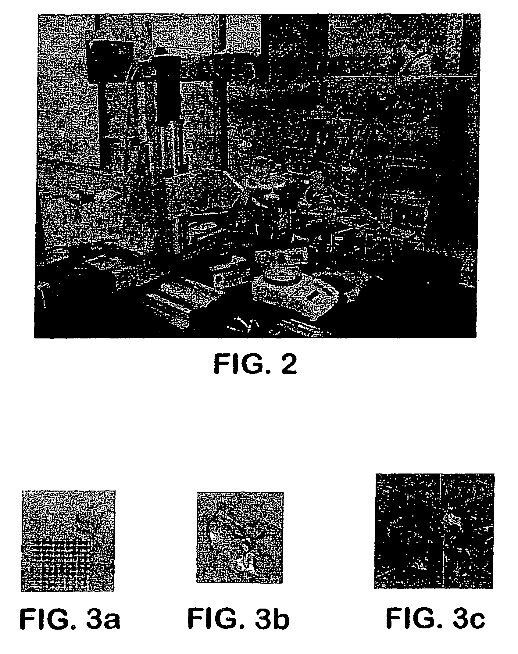
[0069]The apparatus depicted in FIG. 2 was used to construct various three-dimensional biopolymer based tissue scaffolds.

[0070]For example, shown in FIG. 7 are, several three-dimensional hydrogel scaffolds (10 layers, calcium alginate), extruded as a 3% (w / v) alginate filament within a cross-linking solution (FIG. 3a) and simple alginate geometrical pattern (FIG. 3b). Depending upon the size of the syringe nozzle, the pressures used, and the type of deposition method (extrusion), alginate filaments within the 30-40 micron range (FIG. 3c) were created for 3% (w / v) sodium alginate solution with a 5% (w / v) calcium chloride cross-linking solution, at 0.50 psi.

[0071]Further, cell deposition / extrusion studies were conducted by extruding alginate hydrogel mixed with human endothelial cells at a cell concentration: 750,000 cells / ml with sodium alginate: 1.5% (w / v), nozzle: EFD 200 μm at pressure: 2 psi, deposition speed: 10 mm / s, and calcium chloride: 5% (w / v) (see FIG. 4). Experiments were...


PUM

PropertyMeasurementUnit
sizeaaaaaaaaaa
pressureaaaaaaaaaa
MRIaaaaaaaaaa

Abstract

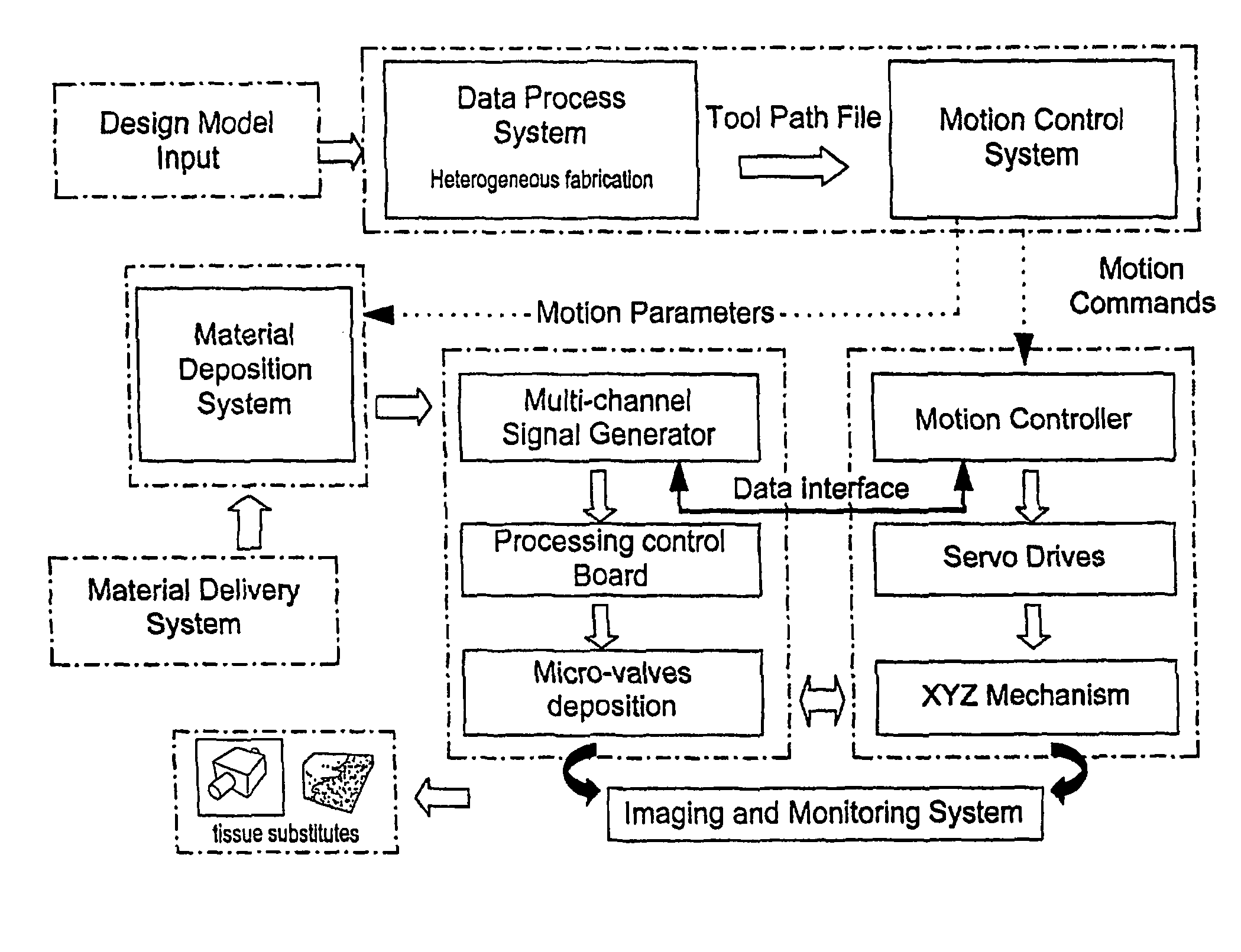
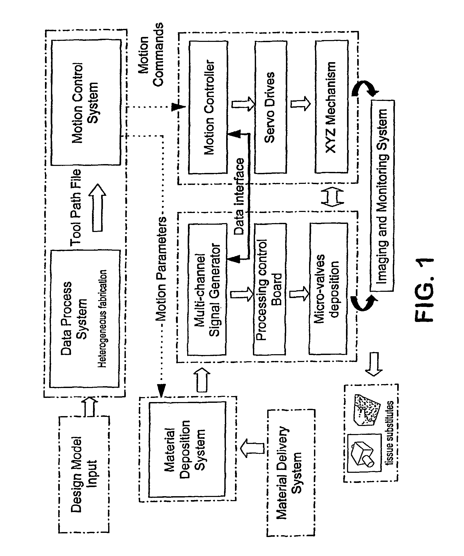
A process and apparatus are provided for manufacturing complex parts and devices which utilize a CAD environment to design a part or device to be created (FIG. 1); Boolean, scaling, smoothing, mirroring, or other operations to modify the CAD design; a software interface to convert the CAD designed part (Data Process System) or device into a heterogeneous material and multi-part assembly model (Design Input Model) which can be used for multi-nozzle printing; and a multi-nozzle system to print the designed part or device using different, specialized nozzles (Tissue substitutes).

Description

[0001]This patent application claims priority to U.S. Provisional patent application Ser. No. 60 / 520,272, filed Nov. 14, 2003, which is herein incorporated by reference in its entirety.FIELD OF THE INVENTION[0002]The present invention provides methods and apparatus for manufacturing complex devices for use in areas including, but not limited to, tissue engineering, organ / cell printing, tissue scaffolds, tissue cultures, biochips, biosensors, cytotoxicity test samples, and other fields that are currently limited by conventional methods of manufacture. The present invention provides methods and apparatus which integrate computer-aided design; Boolean, scaling, mirroring, smoothing, and / or other modifying operations; Magnetic Resonance Imaging (MRI) / Computed Tomography (CT) and other patient specific data import capabilities; heterogeneous material and multi-part assembly capabilities; biomimetic and non-biomimetic design capabilities; multiple types of nozzles capable of handling a wi...

Claims


Application Information

Patent Timeline
Patent Type & Authority Patents(United States)
IPC IPC(8): G06F17/50B29C41/52B29C41/00G06G7/48B29C67/00A01N63/00
CPCG06F17/50B29C41/52B29C67/0059A61K47/36G05B19/042C12N5/0062B29C64/112C12N2533/74G06F30/00B29C64/393B29C64/106G06G7/48B33Y50/02C12N5/0691C12N2513/00G05B19/4099G05B2219/35134G05B2219/49007
Inventor SUN, WEINAM, JAE HYUNDARLING, ANDREW LEETEKHALIL, SAIF
Owner DREXEL UNIV
Learn More