
Method for testing a thermography apparatus, designed for carrying out a thermography method, for its correct operation, test component therefor and method for its production

a thermography apparatus and thermography technology, applied in the field of methods, can solve the problems of inability to produce components, and inability to accurately test the thermography apparatus, etc., and achieve the effects of ensuring the accuracy of the thermography apparatus, ensuring the accuracy of the thermography method, and ensuring the correct operation

Inactive Publication Date: 2013-12-31
SIEMENS AG
View PDF25 Cites 2 Cited by
  • Summary
  • Abstract
  • Description
  • Claims
  • Application Information

AI Technical Summary

Benefits of technology

The present invention provides a method for testing a thermography apparatus for its capacity to detect delaminations. This is achieved by using a mask with openings of defined shape and size to cover the turbine component, and producing auxiliary layers with a defined size and shape. The auxiliary layers can be produced economically and with sufficient precision using atmospheric plasma spraying. The test component can be produced with any desired number of defects, of which the size, shape, and intensity of the delamination can be controlled. The use of an auxiliary layer greatly assists controlled production of the delamination, and the test method offers the advantage that a wide range of different delaminations can be tested by means of a single test component, and the accuracy of the test method is increased compared with the prior art.

Problems solved by technology

In this case, good bonding of the layer in question onto the underlying substrate is of great importance, since local disbonding of the layer increases the risk of flaking, so that the underlying substrate material is directly exposed to the thermally highly stressful ambient conditions, which necessitates premature replacement of the corresponding component.

Method used


Image

  • Method for testing a thermography apparatus, designed for carrying out a thermography method, for its correct operation, test component therefor and method for its production
  • Method for testing a thermography apparatus, designed for carrying out a thermography method, for its correct operation, test component therefor and method for its production
  • Method for testing a thermography apparatus, designed for carrying out a thermography method, for its correct operation, test component therefor and method for its production

Examples


Embodiment Construction

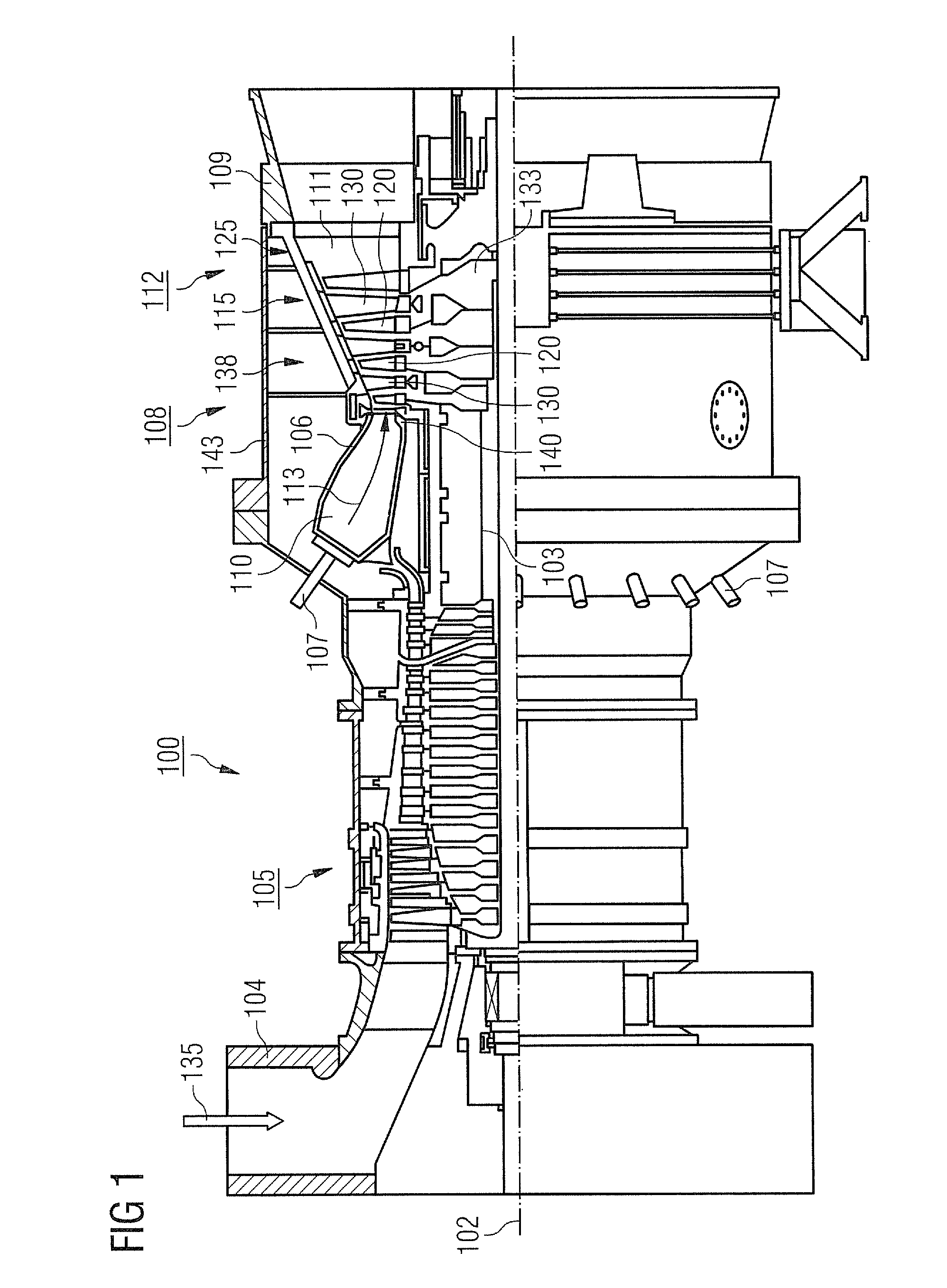
[0037]FIG. 1 shows a gas turbine 100 by way of example in a partial longitudinal section.

[0038]The gas turbine 100 internally comprises a rotor 103, which will also be referred to as the turbine rotor, mounted so as to rotate about a rotation axis 102 and having a shaft 101.

[0039]Successively along the rotor 103, there are an intake manifold 104, a compressor 105, an e.g. toroidal combustion chamber 110, in particular a ring combustion chamber, having a plurality of burners 107 arranged coaxially, a turbine 108 and the exhaust manifold 109.

[0040]The ring combustion chamber 110 communicates with an e.g. annular hot gas channel 111. There, for example, four successively connected turbine stages 112 form the turbine 108.

[0041]Each turbine stage 112 is formed for example by two blade rings. As seen in the flow direction of a working medium 113, a guide vane row 115 is followed in the hot gas channel 111 by a row 125 formed by rotor blades 120.

[0042]The guide vanes 130 are fastened on an...


PUM

PropertyMeasurementUnit
thicknessaaaaaaaaaa
thicknessesaaaaaaaaaa

Abstract

A test component coated with a coating system is provided. In at least one defined region of the test component, there is a delamination having defined properties deliberately introduced into the coating system. The test component may be employed in a method for testing a thermography apparatus that is designed for carrying out a thermography method, for its correct operation with a view to the detection of delaminations. In order to test the thermography apparatus, the at least one defined delamination of the coating system is detected on the test component by using the thermography method employed in the thermography apparatus.

Description

CROSS REFERENCE TO RELATED APPLICATIONS[0001]This application claims priority of European Patent Office application No. 10177354.7 EP filed Sep. 17, 2010, which is incorporated by reference herein in its entirety.FIELD OF INVENTION[0002]The present invention relates to a method for testing a thermography apparatus, designed for carrying out a thermography method, for its correct operation. The invention furthermore relates to a test component, which is used in the test method, and to a method for producing such a test component.BACKGROUND OF INVENTION[0003]Components which are exposed to high thermal stresses during their use, for instance turbine guide vanes or rotor blades (both referred to below as turbine blades for brevity), are generally made of refractory nickel- or cobalt-based alloys. Although such alloys have a high thermal load-bearing capacity, the components generally also need to be provided with a corrosion- and / or oxidation-inhibiting layer in order to extend their l...

Claims


Application Information

Patent Timeline
Patent Type & Authority Patents(United States)
IPC IPC(8): G01K15/00C23C2/38
CPCG01N25/72C23C28/00C23C28/04C23C4/005C23C4/02Y02T50/67C23C28/3455C23C28/3215C23C28/042C23C28/345C23C4/01Y10T428/265Y10T428/24942Y02T50/60
Inventor LADRU, FRANCIS-JURJENSIEBERT, BERNHARD
Owner SIEMENS AG
Learn More