Flight control system mode and method providing aircraft speed control through the usage of momentary on-off control

a control system and aircraft technology, applied in the field of human-machine aircraft control user interfaces, can solve the problems of inability to provide suitable landing flare characteristics, longitudinal control laws that require a great deal of pilot skill to operate, and the earliest control interfaces are very simple, so as to achieve safe and convenient flight, improve safety, and improve safety. the effect of flight safety and economics

Active Publication Date: 2013-12-10
EMBRAER SA
View PDF13 Cites 8 Cited by
  • Summary
  • Abstract
  • Description
  • Claims
  • Application Information

AI Technical Summary

Benefits of technology

[0009]In an exemplary illustrative non-limiting implementation, a control law based on load factor control is presented. For example, the flight control law computes the load factor command based on a set of flight parameters and on the sensed position of the pilot inceptor. The pilot inceptor may be any of a plurality of devices used in aeronautics industry to serve as an interface with a human pilot, e.g. columns, mini-columns, central sticks, control yokes, or side-sticks. The flight parameters include, but are not limited to, in this example, flaps position, calibrated airspeed and dynamic pressure.
[0010]The technology herein aims to propose a flight control system and a method of adding positive speed stability characteristics to a longitudinal control law when the aircraft is set to the approach configuration, i.e. when the flap lever is set to the landing position and landing gears are down, without requiring use of radio altimeter information. The effort of trimming the aircraft speed during approach can be extremely reduced by the usage of a momentary on-off switch in the sidestick.
[0011]The exemplary illustrative non-limiting technology described herein is a flight control system that adds positive static speed stability to longitudinal control law when aircraft is configured for landing, i.e. flap levers in the landing position and landing gears down-locked.
[0012]Since the illustrative reconfigured control law for landing no longer provides auto-trim capability, a manual trimming process is performed similarly to a conventional aircraft: the pilot will be required to keep the longitudinal inceptor in a pulled back position in order to reduce the aircraft speed.
[0013]Once the target speed is reached, the pilot can set this new speed reference value by pressing the momentary on-off switch located in the sidestick, which reduces significantly the pilot workload. As long as the momentary switch is pressed, the reference speed is continuously resynchronized to the current airspeed. When the switch is released, the current airspeed is latched as a new reference.
[0014]In order to avoid transients in the primary surface, a rate limiter is applied while the new reference speed is still not reached by the aircraft. The reference speed may be indicated in the primary flight display as a speed bug in the speed tape. The engagement of the landing mode is indicated as a flag also in the primary display.
[0015]A non-limiting advantage of the illustrative solution is a control law that provides suitable handling qualities during both approach and flare flight phases. Therefore, the radio altimeter is no longer needed as a trigger for the flare control law. This eliminates the failure case of using erroneous height information and allows the dispatch of the aircraft with one failed radio altimeter without reduction of safety margins.
[0016]In one example non-limiting implementation, no additional hardware or physical parts are needed to implement the proposed solution when compared to the aircraft in the basic configuration.
[0017]An example non-limiting illustrative system provides a flight control system mode and method that provides aircraft speed control through the usage of a momentary on-off switch in the pilot inceptor. When configured for landing, the engagement of the proposed mode adds positive static speed stability to a longitudinal control law that controls a load factor demand. Such an illustrative system can provide:

Problems solved by technology

The earliest control interfaces were very simple but required a great deal of pilot skill to operate.
More specifically, longitudinal control laws often do not provide suitable landing flare characteristics, and in particular speed stability during landing.
However, this sort of solution has occasionally presented in-service events such as early flare activation during the approach due to erroneous height indication.
Radio altimeter information can be corrupted by external and internal causes, such as water flow dirt or ice accretion on antennas, degraded connectors, reflectivity variations in terrain and contaminated runways.
Another setback related to the usage of radio altimeter in critical flight controls application is the dependency on redundant sensors to guarantee the necessary system integrity.
In other words, dispatching with one radio altimeter failed may not be possible to guarantee the necessary safety margins.
This means that a change in the speed can only be accomplished while force is applied in the longitudinal pilot inceptor.

Method used


Image

  • Flight control system mode and method providing aircraft speed control through the usage of momentary on-off control
  • Flight control system mode and method providing aircraft speed control through the usage of momentary on-off control
  • Flight control system mode and method providing aircraft speed control through the usage of momentary on-off control

Examples


Embodiment Construction

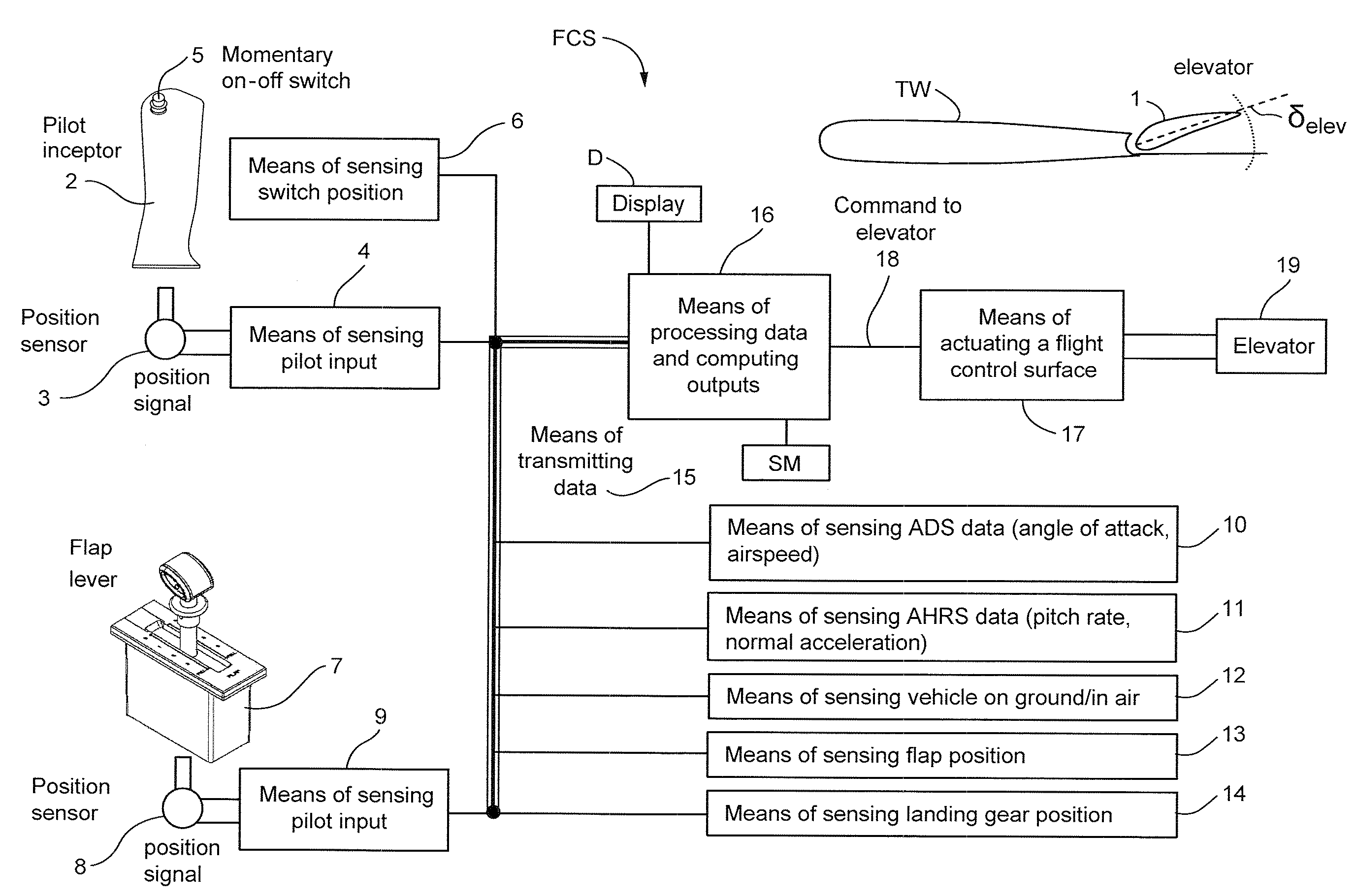
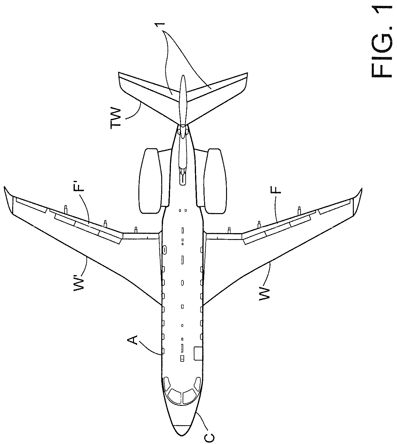
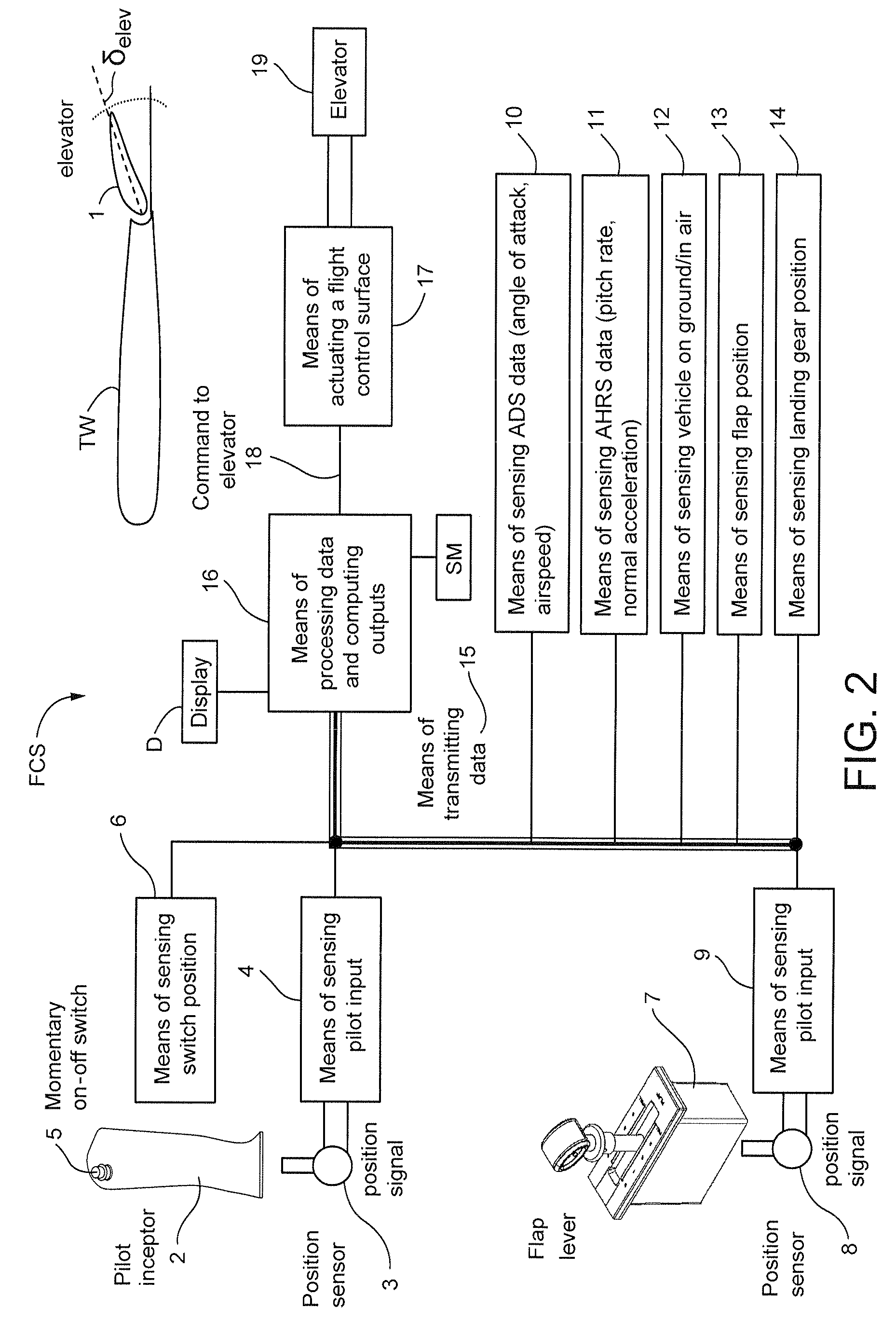
[0032]FIG. 1 shows an example: a twin turbo-fan engines civilian transporter aircraft A. Two elevators (1) are installed in the horizontal tail wing TW for pitch control, and two flaps F are installed in the main wings W for controlling lift and to slow the aircraft during landing. The tail elevators 1 control the pitch of the aircraft A during takeoff, flight and landing. The pilot in the cockpit C interacts with the aircraft A to control the control surfaces including flaps F and elevators 1. A fly-by-wire electronic flight control system accepts pilot input (e.g., through manual manipulation of a flap lever 7 and a pilot interceptor 2, see FIG. 2), and uses automatic control laws typically implemented by a digital (computer) processing system to control actuators that in turn control the positions of flaps F and elevators 1. When landing, landing gear (not shown) on the aircraft A's underside descends from a compartment in the belly of the aircraft to provide wheels that contact ...


PUM


Abstract

A longitudinal control law is designed to optimize the flying qualities when aircraft is set to approach configuration, i.e. when the flap lever is set to the landing position and landing gears are locked down. Under such circumstances, the effort of trimming the aircraft speed can be extremely reduced by the usage of a momentary on-off switch or other control in the sidestick, instead of or in addition to a conventional trim up-down switch, making easier the task of airspeed selection by the pilot. This control law provides excellent handling qualities during approach and landing, with the benefit of not needing or using radio altimeter information in safety-critical applications.

Description

CROSS-REFERENCES TO RELATED APPLICATIONS[0001]N / ASTATEMENT REGARDING FEDERALLY SPONSORED RESEARCH OR DEVELOPMENT[0002]N / AFIELD[0003]The technology herein relates human-machine aircraft control user interfaces, and more particularly to a closed-loop speed control user interface system using a momentary on-off switch. Exemplary illustrative non-limiting implementations are systems, mechanisms and methods to be used in a flight vehicle equipped with a closed loop control law in the longitudinal axis.BACKGROUND AND SUMMARY[0004]The control interface between a pilot and the air control surfaces of an aircraft has received much attention over the history of aviation. The earliest control interfaces were very simple but required a great deal of pilot skill to operate. Modern “fly by wire” interfaces make use of a host of electronics to assist the pilot and make flight safer and more economical. In “fly by wire”, the pilot interacts with an electronic user interface that then controls actua...

Claims


Application Information

Patent Timeline
Patent Type & Authority Patents(United States)
IPC IPC(8): B64C13/00
CPCG05D1/0808G05D13/62G05D1/0676
Inventor CALDEIRA, FABRICIO REISCAMPOS, MARCOS VINICIUSANDRIOLI, JR., RENEU LUIZCARVALHO, WAGNER DE OLIVEIRAGANGSAAS, DAGFINNCAMELIER, EDUARDOSIQUEIRA, DANIELRUBIANO, LUCAS
Owner EMBRAER SA
Why Eureka
Try Eureka