
Device for splitting a light beam

a light beam and device technology, applied in lasers, laser details, instruments, etc., can solve the problems of unfavorable use of incident light beams, substantial power losses, undesired refraction phenomena, etc., and achieve the effect of effective configuration

Active Publication Date: 2013-11-19
LIMO DISPLAY GMBH
View PDF11 Cites 0 Cited by
  • Summary
  • Abstract
  • Description
  • Claims
  • Application Information

AI Technical Summary

Benefits of technology

The device effectively splits unpolarized light beams into subbeams with equal intensity and minimal refraction, allowing for precise control over subbeam intensity ratios and beam parameters, while being insensitive to variations in the laser source.

Problems solved by technology

These have a particular disadvantage in that they can only reasonably be used given an incident light beam with a defined polarization.
If a non-polarized laser beam is to be split into a number of subbeams of equal intensity, said laser beam must be polarized before being split by polarization filters, and this causes substantial power losses.
The splitting of a light beam by a plurality of geometric beam splitters such as mirrors can cause undesired refraction phenomena.

Method used


Image

  • Device for splitting a light beam
  • Device for splitting a light beam

Examples


Embodiment Construction

[0022]A Cartesian coordinate system is illustrated in FIG. 1 for the purpose of better orientation.

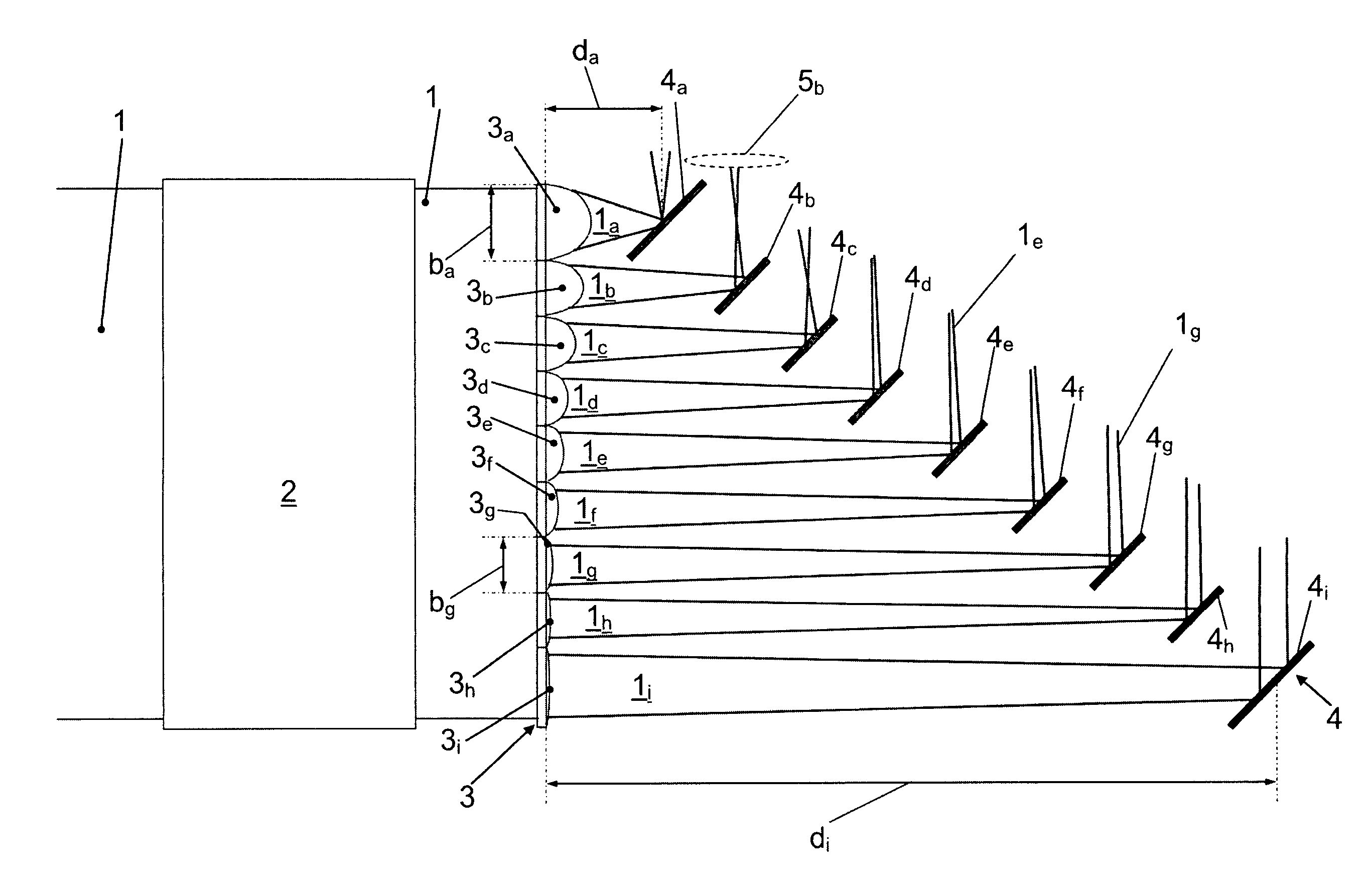
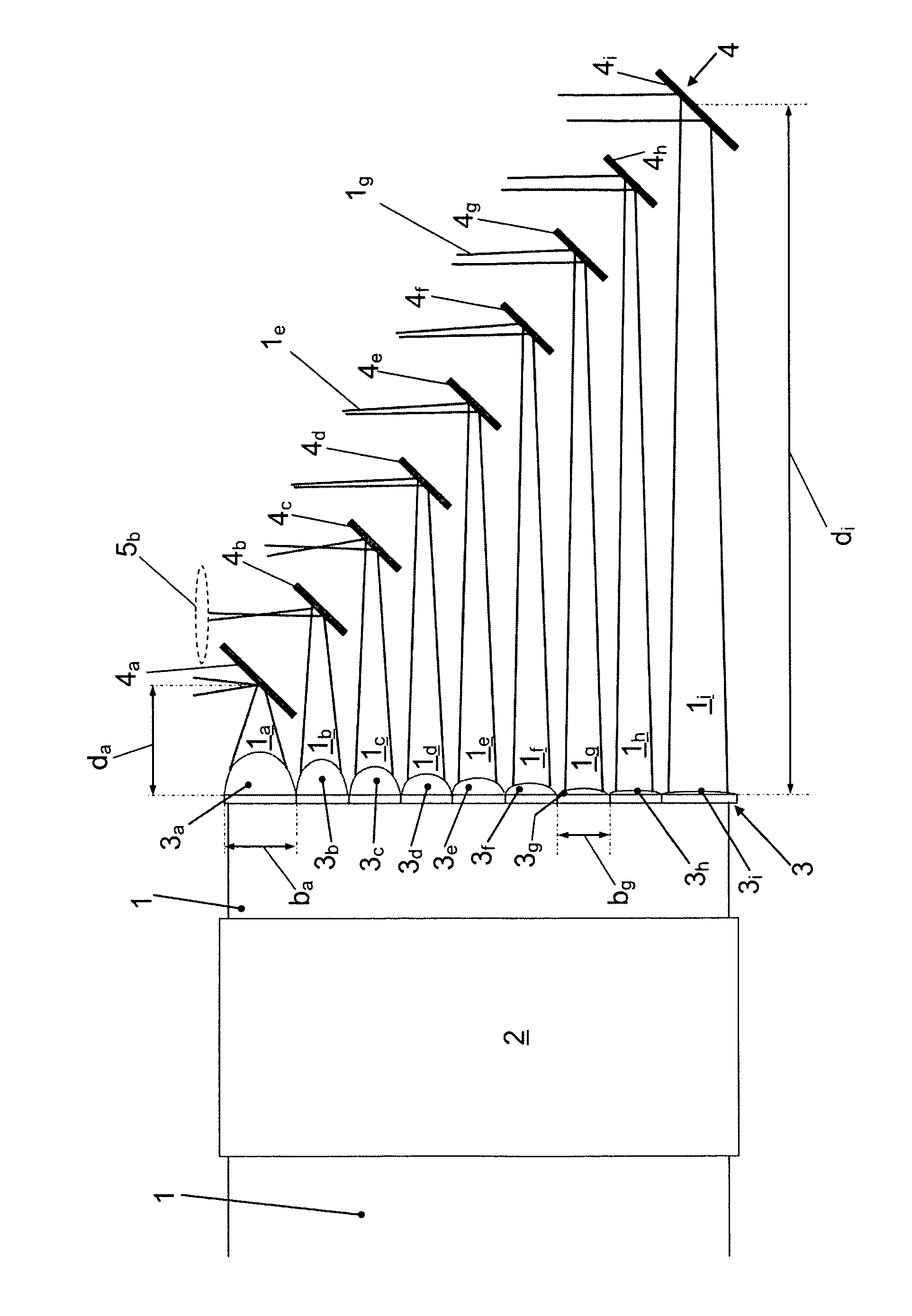
[0023]The device according to the invention is illustrated in FIG. 1. The device is intended to provide for splitting into a number of subbeams 1a to 1i a light beam 1 that is incident in the positive Z-direction, or from the left hand side in FIG. 1, emanates from a high power laser, for example, and is unpolarized, for example. To this end, the device comprises homogenizing means 2 that are indicated merely schematically in FIG. 1. The homogenizing means 2 can have, in the usual way, lens arrays, for example, two cylindrical lens arrays arranged consecutively in the propagation direction Z of the light beam, and Fourier lenses for superimposing the subbeams that have passed through the cylindrical lens arrays.

[0024]If the light beam 1 is to be split into subbeams in only one direction such as, for example, the X-direction in FIG. 1, it suffices to homogenize the light beam 1 with reg...


PUM


Abstract

Device for splitting a light beam (1), including at least one lens array (3) with a plurality of lenses (3a-3i) of which at least two have a mutually differing, positive focal length, wherein the light beam (1) that is to be split can pass through the at least one lens array (3) and form at least some mutually separated, at least partially convergent subbeams (1a-1i) after passing through the plurality of lenses (3a-3i), and deflecting means (4) with a plurality of deflecting elements that are arranged downstream of the at least one lens array (3) and can deflect at least some of the subbeams (1a-1i), wherein at least two of the deflecting elements have a different spacing (da-di) from the at least one lens array (3).

Description

BACKGROUND OF THE INVENTION[0001](1) Field of the Invention[0002]The present invention relates to a device for splitting a light beam.[0003]Definitions: In the propagation direction of the light beam or laser radiation signifies the mean propagation direction of the light beam or the laser radiation, in particular when this is not a plane wave, or is at least partially divergent or convergent. Unless otherwise expressly specified, light beam, subbeam or beam does not signify an idealized beam of geometric optics, but a real light beam such as, for example, a laser beam with a Ganssien profile or a modified Ganssien profile that has an extended beam cross section not an infinitesimally small one.[0004]2) Description of Related Art[0005]The splitting of a light beam such as, for example, a laser beam of a high energy laser, into a plurality of subbeams is frequently performed in the prior art by polarization beam splitters. These have a particular disadvantage in that they can only re...

Claims


Application Information

Patent Timeline
Patent Type & Authority Patents(United States)
IPC IPC(8): G02B27/10
CPCG02B3/0006G02B27/0905G02B27/0961G02B27/0966G02B27/0977H01S3/05H01S3/02
Inventor MITRA, THOMASFRUNDT, JANA
Owner LIMO DISPLAY GMBH
Learn More