Oscillator with MEMS resonator
a technology of oscillator and resonator, applied in the field of oscillator, can solve the problems of reduced size, long delivery time, poor yield, etc., and achieve the effect of good phase noise characteristics
- Summary
- Abstract
- Description
- Claims
- Application Information
AI Technical Summary
Benefits of technology
Problems solved by technology
Method used
Image

Examples
first embodiment
2. First Embodiment
[0063]Hereinafter, a MEMS oscillator according to a first embodiment will be described.
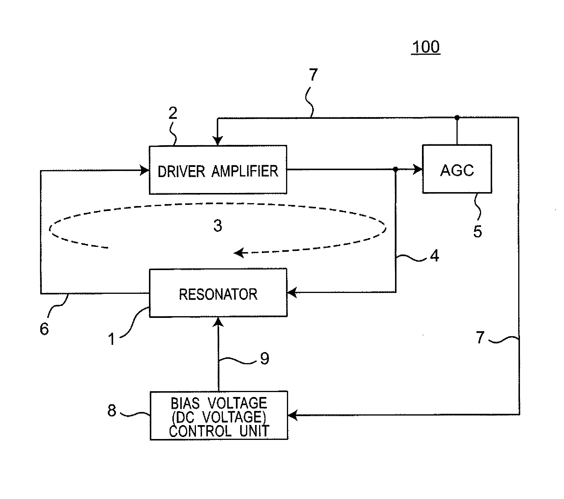
[0064]FIG. 3 is a block diagram illustrating the structure of a MEMS oscillator 100 according to the first embodiment. The MEMS oscillator 100 includes a MEMS resonator 1 as a resonant circuit, a driver amplifier 2 as an amplification circuit, an auto gain control unit (AGC) 5 which is adapted to monitor the amplitude of an output (an oscillation signal 4) from the driver amplifier 2 and to control the gain of the driver amplifier 2, and a bias-voltage control unit 8 which is adapted to derive the operating temperature of the MEMS resonator 1 based on an amplitude control signal outputted from the AGC 5 and to control a bias voltage (a DC voltage VDc in FIG. 17) applied to an oscillating member (vibrator) in the MEMS resonator 1 based on the operating temperature. The MEMS resonator 1 and the driver amplifier 2 form a closed loop 3, which forms a feedback type oscillation circui...
second embodiment
3. Second Embodiment
[0078]Hereinafter, a MEMS oscillator according to a second embodiment will be described.
[0079]FIG. 9 is a block diagram illustrating the structure of a MEMS oscillator 200 according to the second embodiment. The MEMS oscillator 200 includes a MEMS resonator 1, a driver amplifier 2, and an auto gain control unit (AGC) 5, similarly to the MEMS oscillator 100 according to the first embodiment. The MEMS oscillator 200 includes a bias-voltage control unit 8a which is adapted to derive the operating temperature of the MEMS resonator 1 based on an amplitude control signal outputted from the AGC 5 and, further, is adapted to control the AGC 5 and a bias voltage (a DC voltage VDC in FIG. 17) applied to an oscillating member of the MEMS resonator 1 based on this operating temperature, instead of the bias-voltage control unit 8 in the MEMS oscillator 100.
[0080]Similarly to the bias-voltage control unit 8 according to the first embodiment, the bias-voltage control unit 8a va...
third embodiment
4. Third Embodiment
[0090]Hereinafter, a MEMS oscillator according to a third embodiment will be described.
[0091]The MEMS oscillator 300 according to the present embodiment illustrated in FIG. 11 is adapted to variably control the bias voltage applied to an oscillating member of a MEMS resonator 1, based on the operating temperature, similarly to the MEMS oscillator 100. By doing this, the MEMS oscillator according to the present embodiment can maintain the peak gain of the MEMS resonator constant, at any operating temperatures.
[0092]The MEMS oscillator 300 according to the present embodiment includes a temperature sensor 11 for measuring the operating temperature of the MEMS resonator 1, in addition to the same structure as that of the MEMS oscillator 100. The temperature sensor 11 outputs the measured operating temperature of the MEMS resonator 1, as a temperature information signal 12, to a bias-voltage control unit 8s.
[0093]The bias-voltage control unit 8s is adapted such that t...
PUM
 Abstract
Description
Claims
Application Information
 - R&D
- Intellectual Property
- Life Sciences
- Materials
- Tech Scout
- Unparalleled Data Quality
- Higher Quality Content
- 60% Fewer Hallucinations
Browse by: Latest US Patents, China's latest patents, Technical Efficacy Thesaurus, Application Domain, Technology Topic, Popular Technical Reports.
© 2025 PatSnap. All rights reserved.Legal|Privacy policy|Modern Slavery Act Transparency Statement|Sitemap|About US| Contact US: help@patsnap.com