
Turbocharger overheating protection device and method of its manufacture

a technology of overheating protection device and turbocharger, which is applied in the direction of heat measurement, instruments, machines/engines, etc., can solve the problem that the exposed connecting wire cannot withstand the high thermal and mechanical load of the turbocharger

Inactive Publication Date: 2013-10-01
HERAEUS NEXENSOS GMBH
View PDF28 Cites 9 Cited by
  • Summary
  • Abstract
  • Description
  • Claims
  • Application Information

AI Technical Summary

Benefits of technology

[0006]The object of the present invention is to shorten the response time and to provide a simpler design, which withstands lower temperature requirements at increased vibration loads.
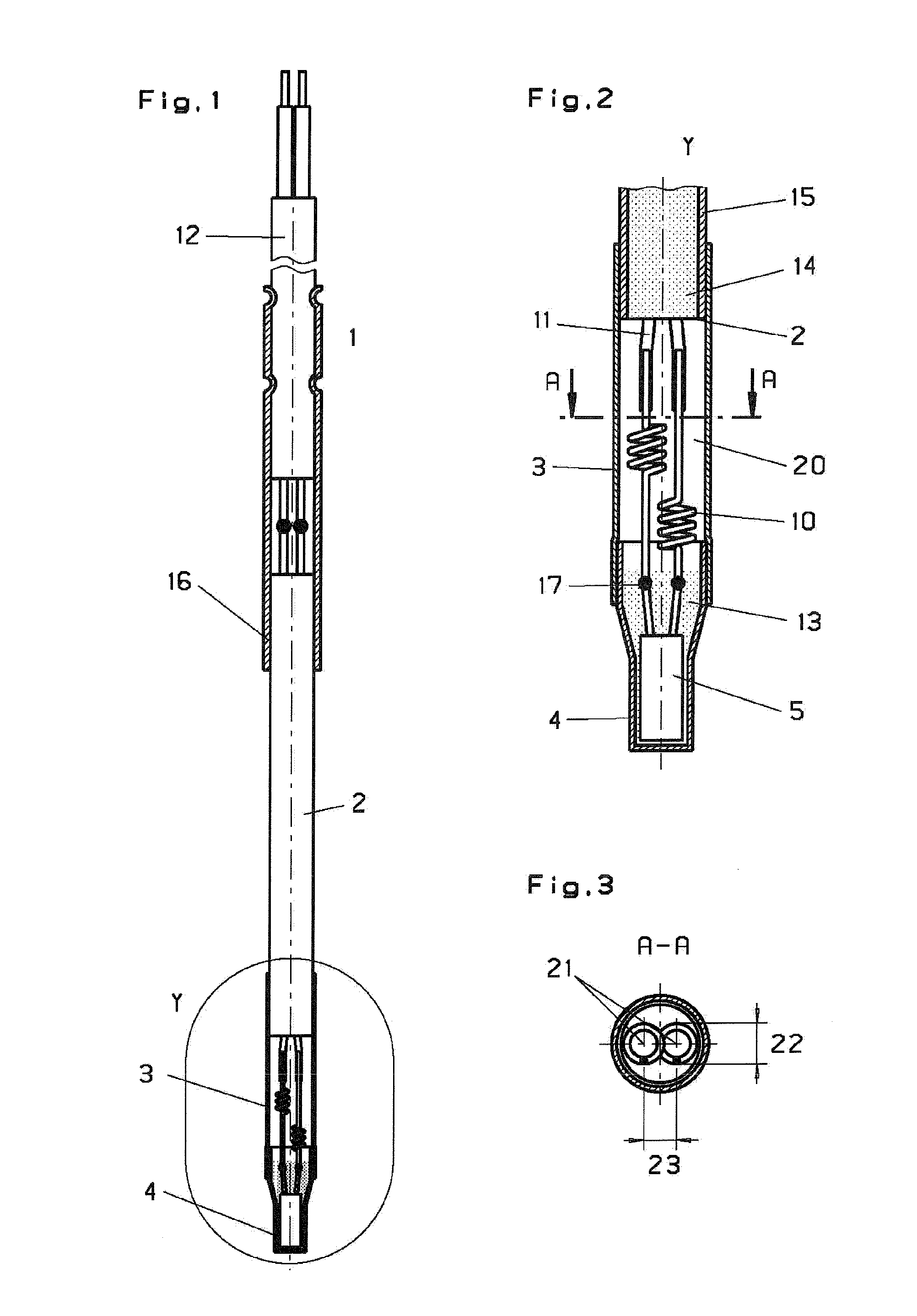
[0008]To achieve the object, according to the invention, the springs are arranged such that the coils cannot touch each another. This avoids the elaborate arrangement of the coils around guide axes. In particular, the spring region according to the invention exhibits a point symmetry relative to the arrangement of the springs to each other, i.e., in contrast to the previously known mirror symmetry. In this way, the coils can also be arranged point-symmetrically to each other, if two different, namely point-symmetrical coils, are used. Preferably, identically constructed springs are used, which means that the coils in the point-symmetrical arrangement of the coil regions are arranged rotation-symmetrically to each other. An air space between a casting in a measuring tip and a mineral-insulated cable (MIL) present around the springs and limited by a sleeve provides higher measurement accuracy. This is based on the induced thermal decoupling between the casting and the mineral-insulated cable. The point-symmetrical arrangement of the coiled regions of the springs relative to each other allows overlapping of their main axes.
[0016]If the two coil springs are arranged staggered in their longitudinal directions adjacent to each other, the airspace is used more efficiently. In particular, the air space is slimmed down and the measurement accuracy and response time are thereby concomitantly improved. The slimming down also allows a saving of nickel, particularly a thinner mineral-insulated cable, e.g. a diameter of 4.5 mm to 3 mm. Incidentally, there results a shortening of the mineral-insulated cable. In coil springs, whose coils are located only in one half of the spring, the coils of one spring are arranged staggered in the longitudinal direction relative to the coils of the other spring.
[0017]To prevent overheatings of the turbocharger of diesel engines, whose the turbocharger withstands a temperature range from −50 to +950° C., a turbocharger overheating protection device is provided, comprising a metal housing made of a mineral-insulated cable, a receptacle and a sleeve projecting partly over each of the mineral-insulated cable and the receptacle. Inside the receptacle, a temperature measuring element is completely embedded in ceramic casting. The temperature measuring element is a measuring resistor equipped with connecting wires, such as a film resistor or thermistor.
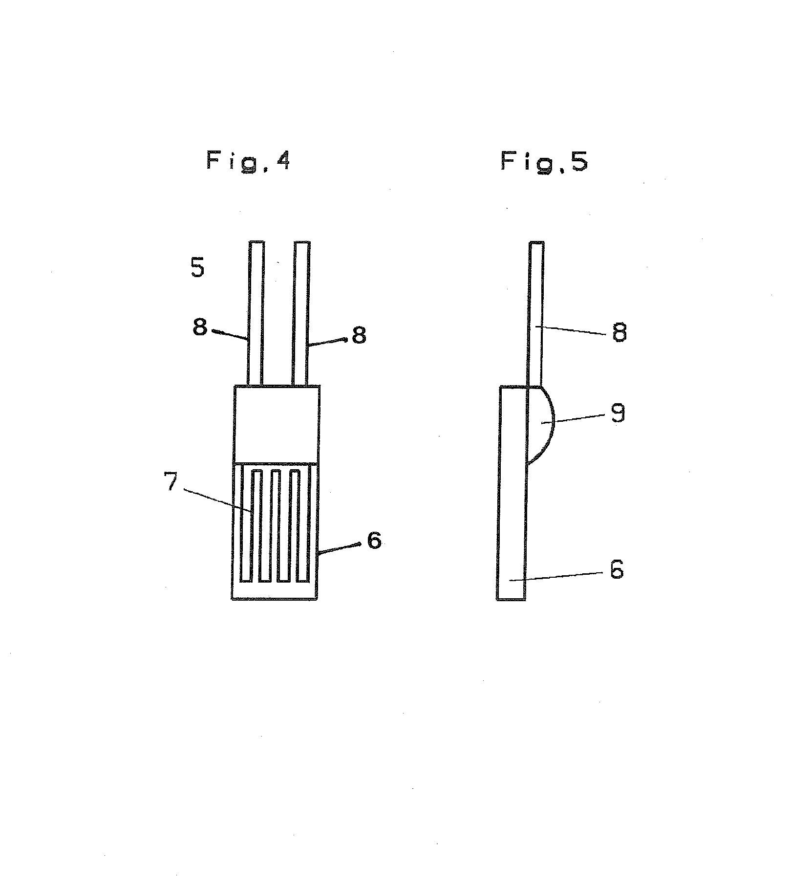
[0020]Preferably, the width of a substrate of a film resistor used as a temperature measuring element is less than 2 mm. Beyond a width of 2 mm, the risk of breakage increases. Below a width of 1 mm, processing is currently still too expensive for mass production. A width of between 1.2 and 1.8 mm, in particular between 1.4 and 1.6 mm has proven itself successful. The length of the substrate should be at least 1.5 times as long as its width, particularly at least twice as long. A ratio of length to width from 2.5 to 3 has proven itself successful.
[0022]The danger of a short circuit of the springs arranged adjacent to each another is reduced by short springs. The short springs do not need to be guided on an axis.

Problems solved by technology

The exposed connecting wires cannot withstand the high thermal and mechanical loads of turbochargers and break in the region of the offset bend.

Method used


Image

  • Turbocharger overheating protection device and method of its manufacture
  • Turbocharger overheating protection device and method of its manufacture
  • Turbocharger overheating protection device and method of its manufacture

Examples


Embodiment Construction

[0029]FIG. 1 shows a temperature sensor 1 as a turbocharger overheating protection device, whose measuring tip can be adapted, particularly bent, corresponding to the requirements of the engine design. This turbocharger overheating protection device with bendable measuring tip has a bendable mineral-insulated cable 2, which is connected via a sleeve 3 to a receptacle 4, in which a film resistor is arranged in a protected manner as a temperature measuring element 5.

[0030]Using a film resistor 5 which is resistant to a temperature of 900° C. based on the brochure “Platinum thin film sensors that convince” [Platin Dünnschichtsensoren, die überzeugen] from Heraeus Sensor Technology GmbH, dated April 2006, a high-temperature-sensor element for a temperature range from −40° C. to 900° C. is created. The critical operating temperature for diesel turbochargers is currently above 850° C.

[0031]The film resistor 5 as temperature measuring element illustrated in FIGS. 4 and 5 consists of a mean...


PUM

PropertyMeasurementUnit
temperatureaaaaaaaaaa
exhaust gas temperatureaaaaaaaaaa
diameteraaaaaaaaaa

Abstract

A housing between mineral-insulated cable and connecting wire in a turbocharger overheating protection device may include the following characteristics:coiled regions of springs (10) arranged point-symmetrically to each other; orthe springs (10) are not placed on axes; orthe coil regions of the coil springs (10) for cushioning the film resistor are shorter than its substrate length and longer than its substrate width; orthe connecting wires of the film resistor are shorter than its substrate length and longer than its substrate width; orthe springs are arranged staggered in their longitudinal direction adjacent to each other; orcoil springs (10) are used, in which the coils are located only in one half of the spring (10) and the coils of one spring are arranged staggered in the longitudinal direction to the coils of the other spring (10).

Description

BACKGROUND OF THE INVENTION[0001]The present invention relates to spring-cushioned measuring resistors, which are embedded within a bushing in a ceramic casting. In particular, the invention relates to a turbocharger overheating protection device for preventing overheatings of the turbocharger of diesel engines whose turbocharger withstands a temperature range of −50 to +950° C., comprising a metal housing made of a mineral-insulated cable (also referred to as MIL), a receptacle and a sleeve projecting partly over each of the mineral-insulated cable and the receptacle, wherein a temperature measuring element is completely embedded in ceramic casting in the receptacle, the temperature measuring element is a measuring resistor or thermistor equipped with connecting wires, the connecting wires are connected by coil springs with the cores of the mineral-insulated cable. Furthermore, the invention relates to a method for manufacturing a turbocharger overheating protection device and its ...

Claims


Application Information

Patent Timeline
Patent Type & Authority Patents(United States)
IPC IPC(8): G01K1/00G01K7/00
CPCF01D21/003G01K1/12G01K7/16F05D2220/40G01K2205/02F02B39/16F01D25/00F02B39/00
Inventor BACHMANN, MARIOWIENAND, KARLHEINZ
Owner HERAEUS NEXENSOS GMBH
Learn More