
Aerosol collection apparatus and methods

a technology of aerosol and collection apparatus, which is applied in the direction of specific gravity measurement, cleaning using liquids, instruments, etc., can solve the problems of inability to detect bioaerosols, particulates toxins or other aerosol particles of interest, and the inability to adhere to sample materials for many kinds of analyses, so as to prevent particle build-up, remove stubborn deposits, and restore optimal efficiency

Inactive Publication Date: 2013-09-24
ENERTECHNIX
View PDF41 Cites 40 Cited by
  • Summary
  • Abstract
  • Description
  • Claims
  • Application Information

AI Technical Summary

Benefits of technology

Enables the collection and analysis of aerosol particles in extremely small droplet volumes, enhancing detection sensitivity and speed, while preventing fouling through acoustic cleaning, thus improving the efficiency and robustness of aerosol monitoring systems.

Problems solved by technology

However, unless first eluted from the impactor surface, these adherent sample materials are not generally accessible for many kinds of analyses.
Inability to elute the sample material in a liquid volume can result in failure to detect a bioaerosol, particulate toxin or other aerosol particle of interest.

Method used


Image

  • Aerosol collection apparatus and methods
  • Aerosol collection apparatus and methods
  • Aerosol collection apparatus and methods

Examples


example 1

Dry Acoustic Cleaning of an Aerosol Concentrator

[0352]An aerosol concentrator with ADL and skimmer of the type shown in co-assigned U.S. Pat. No. 7,875,095 was set up with flowing air and instrumented to monitor backpressure. ASHRAE dust was then introduced into the feed and backpressure was monitored. After a suitable interval, backpressure in the major and minor flow channels had substantially increased. The skimmer assembly was then subjected to acoustic energy using a piezoelectric horn contacted to the body of the skimmer. Backpressure immediately returned to pre-fouling levels. As shown in the table below, backpressure in the major flow channels was seen to rise from 5.5 to 12 inches H2O with increased narrowing due to accumulation of ASHRAE dust in the channels. Upon application of ultrasound to the body of the assembly, backpressure immediately returned to baseline. Similarly, in the minor flow channel, backpressure rose from 0.3 to 1.8 inches H2O, but returned to 0.3 inches...

example 2

Prophylaxis

[0354]In a second example, prophylactic treatment was demonstrated. Using the setup of Example 1, ASHRAE dust was again introduced into an aerosol concentrator. A flow split of 40:1 was used; with 10 Lpm flow rate in the chimneys and 0.25 Lpm in the collector channel. Rather than permit fouling to occur, ultrasound (33 KHz, 50 W) was applied for 1 second at 2 minute intervals. Backpressure was again monitored.

[0355]After 30 minutes, no increase in backpressure was noted in any of the channels of the device. Contrastingly, backpressure had noticeably increased under control conditions without ultrasonic prophylaxis of fouling. Visual inspection confirmed that particle deposits were prevented by periodic ultrasonic treatments.

[0356]

Backpressure, Major FlowBackpressure, Minor FlowExperimentalChannels (inches H20)Channel (inches H20)Intermittent US30Treatment over30 minNegative30.3Control

[0357]The reduced duty cycle (1 sec ON at 2 min intervals) reduced energy consumed in the...

example 3

Timecourse for Fouling Under Heavy Loading

[0359]Using the setup described in the examples above, the data of FIG. 34 was obtained by monitoring backpressure over a thirty minute interval. Backpressure is reported as percent over baseline. Backpressure in the chimney of the untreated channel continued after ten minutes but increases are not shown because the pressure gauge had reached its maximum reading.


PUM


Abstract

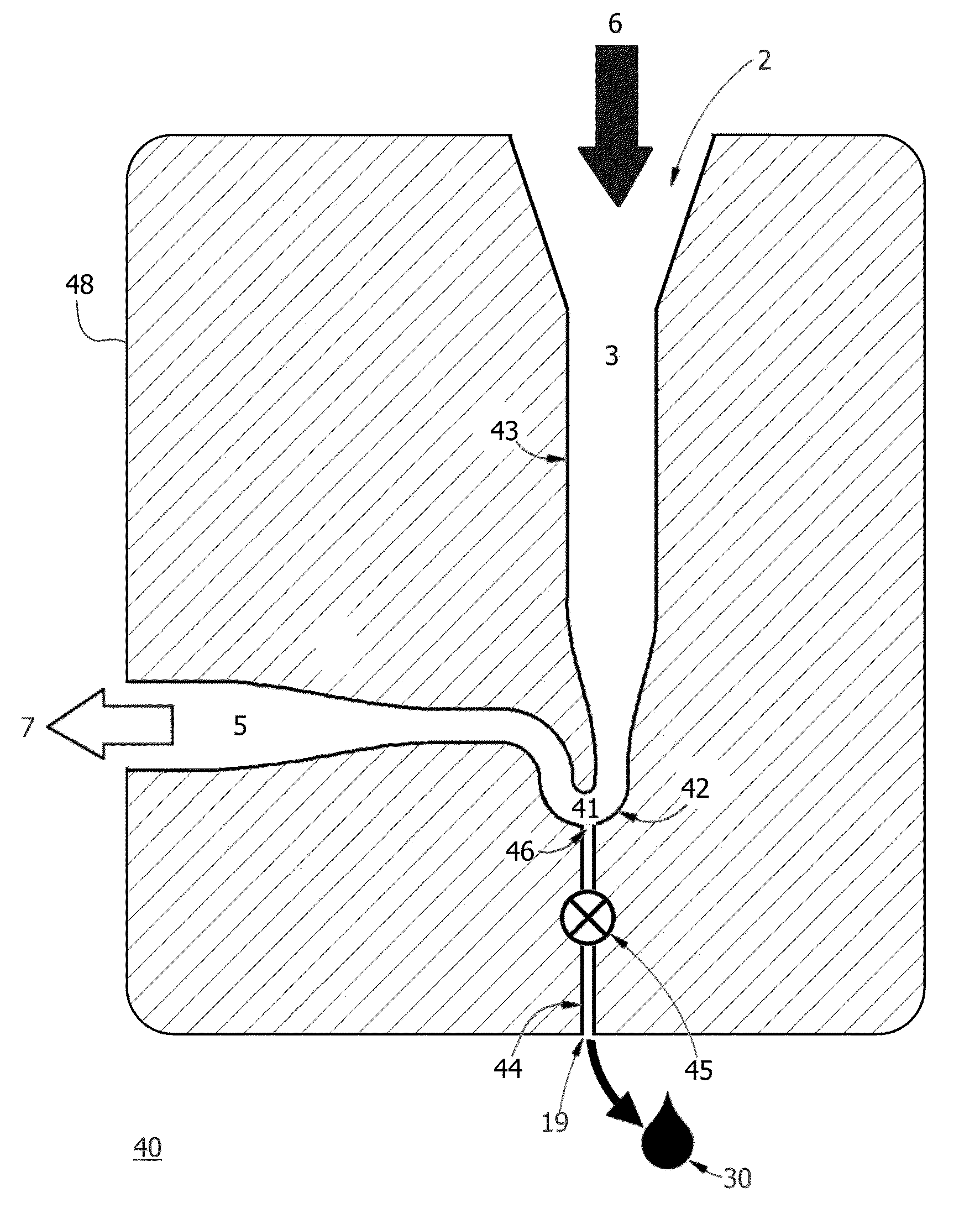
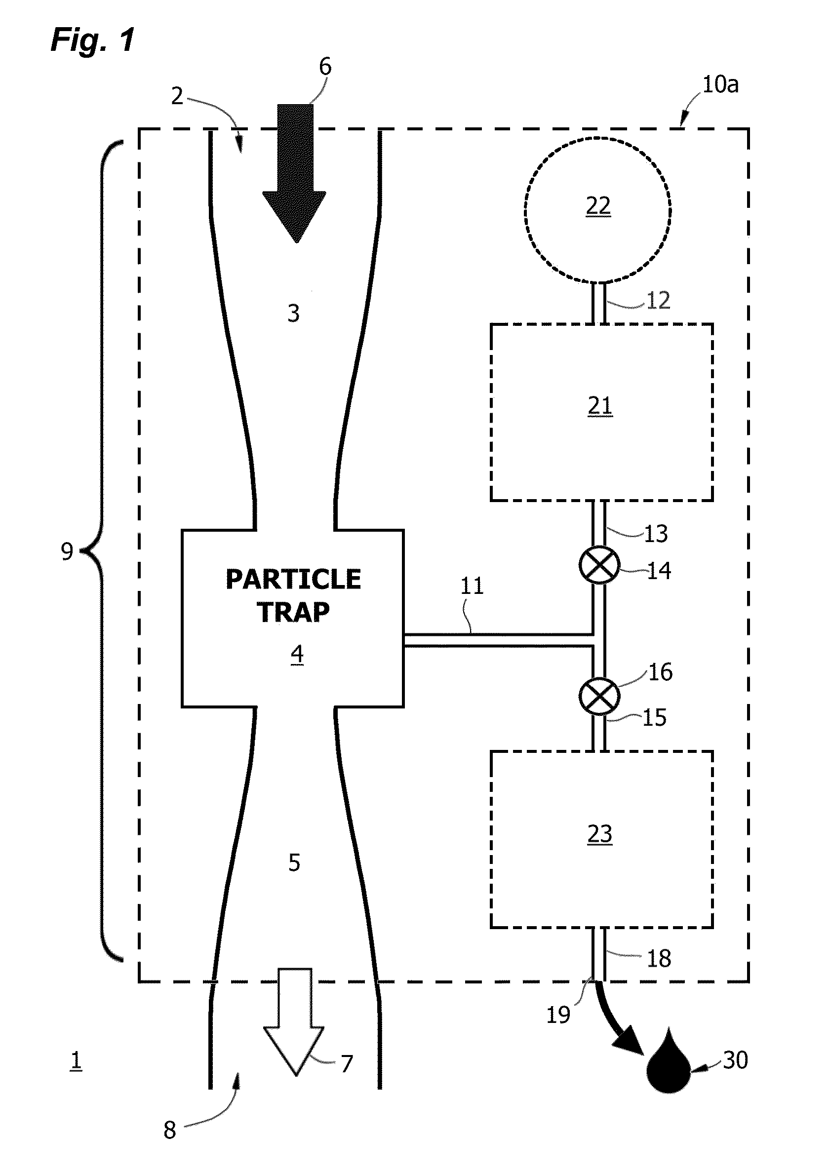
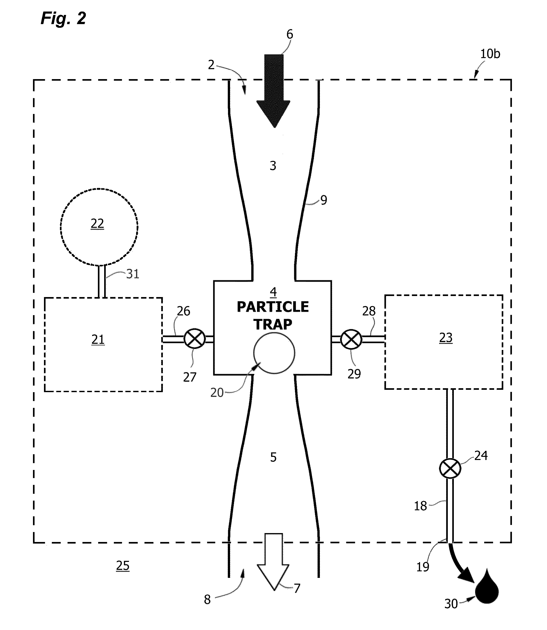
An apparatus or device for collecting aerosol particles from a gas stream, having a collector body enclosing a collector channel, a particle trap in the collector channel, and an injection duct for injecting a discrete microdroplet of an elution reagent. The particle trap may be a centrifugal impactor, a bluff body impactor, or an electrostatic impactor. Aerosol particles are deposited on the surface during collection and are subsequently eluted with a microdroplet or a series of microdroplets as a concentrated liquid sample so that the sample can be analyzed in situ or conveyed to a detector for analysis. The collector serves as an aerosol-to-liquid conversion module as part of an apparatus for detecting and analyzing aerosol particles, and may be used in an integrated environmental threat assessment system, for example for characterization of aerosolized chemical and biological weapons, or for industrial or environmental monitoring.

Description

RELATED APPLICATIONS[0001]The present application is a Continuation-In-Part of U.S. patent application Ser. No. 12 / 364,672 titled “Aerosol Collection and Microdroplet Delivery for Analysis”, filed 3 Feb. 2009, now abandoned, which claims the benefit of priority under 35 USC 119(e) Provisional Pat. Appl. No. 61 / 026,376 filed on 5 Feb. 2008, said patent documents being incorporated herein in entirety for all purposes by reference.GOVERNMENT SUPPORT[0002]The United States Government has rights in this invention pursuant to Grant No. NBCHC060109 awarded by the Department of Homeland Security, and Grant No. 1R43ES016390-01 awarded by the National Institutes of Health.BACKGROUND[0003]Aerosols from natural, anthropogenic and industrial sources have long been recognized as a potential threat to human health; to that list of sources we now must add airborne chemical or biological warfare agents as a source of potentially lethal exposure or terrorist threat. Effective sampling and collection ...

Claims


Application Information

Patent Timeline
Patent Type & Authority Patents(United States)
IPC IPC(8): G01N3/02
CPCB08B3/12B08B7/026G01N1/2202G01N1/2208G01N1/2211G01N15/0266G01N15/0606G01N2001/2223G01N2001/383G01N2015/0038G01N2015/0088G01N2015/0096G01N2015/0261B03C3/017B03C3/08B03C3/12B03C3/41B03C3/47B03C2201/04Y10T137/8376G01N2015/019
Inventor ARIESSOHN, PETER CNOVOSSELOV, IGOR VDENGLER, EVAN
Owner ENERTECHNIX
Learn More