
System, apparatus, program product, and related methods for providing boundary layer flow control

a flow control and boundary layer technology, applied in the direction of air-flow influencers, drag reduction, wings, etc., can solve the problems of poor performance and/or stalling of aircraft engines, flows can affect efficiency, and buffer and fatigue any downstream structures so exposed, so as to reduce drag on aircraft, reduce cross-flow instabilities, and stabilize the flow

Active Publication Date: 2013-09-03
LOCKHEED MARTIN CORP
View PDF14 Cites 23 Cited by
  • Summary
  • Abstract
  • Description
  • Claims
  • Application Information

AI Technical Summary

Benefits of technology

This patent describes various methods and apparatus for creating electrodes with smooth surfaces that minimize drag caused by plasma actuators, and can create precise electrodes. The invention also provides methods for creating separate electrodes that can complement each other and form a net momentum and velocity to the surrounding fluid, while also mitigating cross-flow instabilities on swept wings. These technical advancements can provide a desirable quality in fluid flows across aerodynamic surfaces, reduce drag on aircraft, increase fuel efficiency, and stabilize flow over the wing.

Problems solved by technology

Adverse fluid flows generated over aerodynamic surfaces can buffet and fatigue any downstream structures so exposed.
Additionally, such flows can affect efficiency by increasing drag or resistance over the surface.
Additionally, these adverse fluid flows can be ingested within engine air intakes or other like air inlets leading to poor performance and / or stalling of the aircraft engines.
This approach, however, limits design options and increases vehicle size, weight and cost.
Placing components, such as engines or control surfaces, in non-optimal positions in order to reduce these stresses often results in reduced vehicle performance.
Similarly, adding structural weight to support increased stress loads caused by the flow field vortices also results in reduced vehicle performance.
The devices, however, themselves cause drag which reduces the effectiveness of the devices.
Such devices, however, require pneumatic / fluid conduits and / or manifolds to bring the control jets to regions requiring flow-control authority.
Additionally, utilization of such devices result in added structural weight to supply and support the control jets, which results in reduced vehicle performance.
Specifically, such combustion-driven jet actuators include a combustion chamber that is filled with a combustible mixture which is then ignited, resulting in high pressures inside the chamber and mass expulsion through a chamber orifice.
Besides the necessary fuel and air conduits, such devices also require a fuel storage capability, mechanical valves, and a means for igniting the fuel, which result in added structural weight to supply and support the control jets, which results in reduced vehicle performance.
These devices add additional weight and / or complexity to the air foil design.
As with the mechanical and bimorph synthetic jet actuators, the spark jet actuators also add additional weight and / or complexity to the air foil design.
Such devices, however, result in increased costs, added weight, and increased complexity to the overall system.
In addition, these constructs do not form individual regions that are individually addressable.
Notably, although it is believed by the inventors that such annular-shaped device would provide some functionality if arranged according to various delivery patterns according to various embodiments of the present invention and / or interfaced with control systems described hereinafter and if exposed to air flows with relatively low Reynolds numbers, it is expected that such would not be effective at higher Reynolds numbers.
As such, at a higher Reynolds number, the annular design would be less desirable, as the annular shape would be expected to dictate a requirement for spacing between actuators that would be larger than desired.

Method used


Image

  • System, apparatus, program product, and related methods for providing boundary layer flow control
  • System, apparatus, program product, and related methods for providing boundary layer flow control
  • System, apparatus, program product, and related methods for providing boundary layer flow control

Examples


Embodiment Construction

[0053]The present invention will now be described more fully hereinafter with reference to the accompanying drawings, which illustrate embodiments of the invention. This invention may, however, be embodied in many different forms and should not be construed as limited to the illustrated embodiments set forth herein. Rather, these embodiments are provided so that this disclosure will be thorough and complete, and will fully convey the scope of the invention to those skilled in the art. Like numbers refer to like elements throughout. Prime notation, if used, indicates similar elements in alternative embodiments.

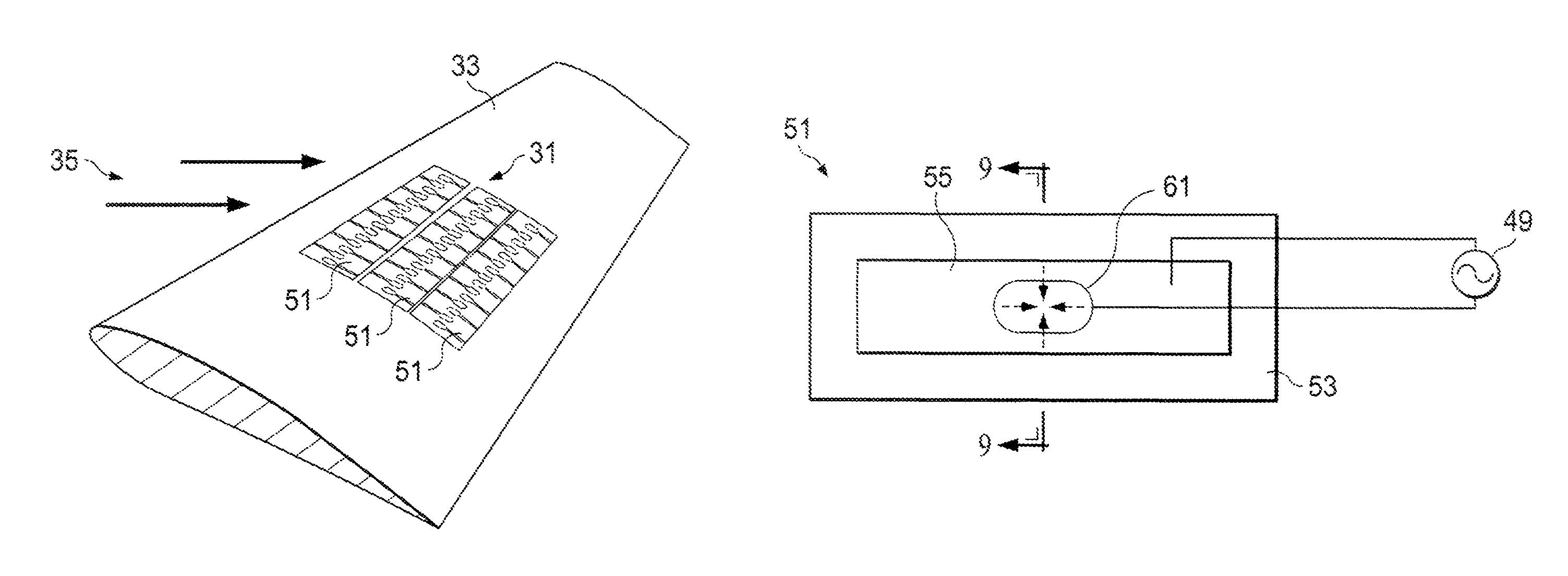
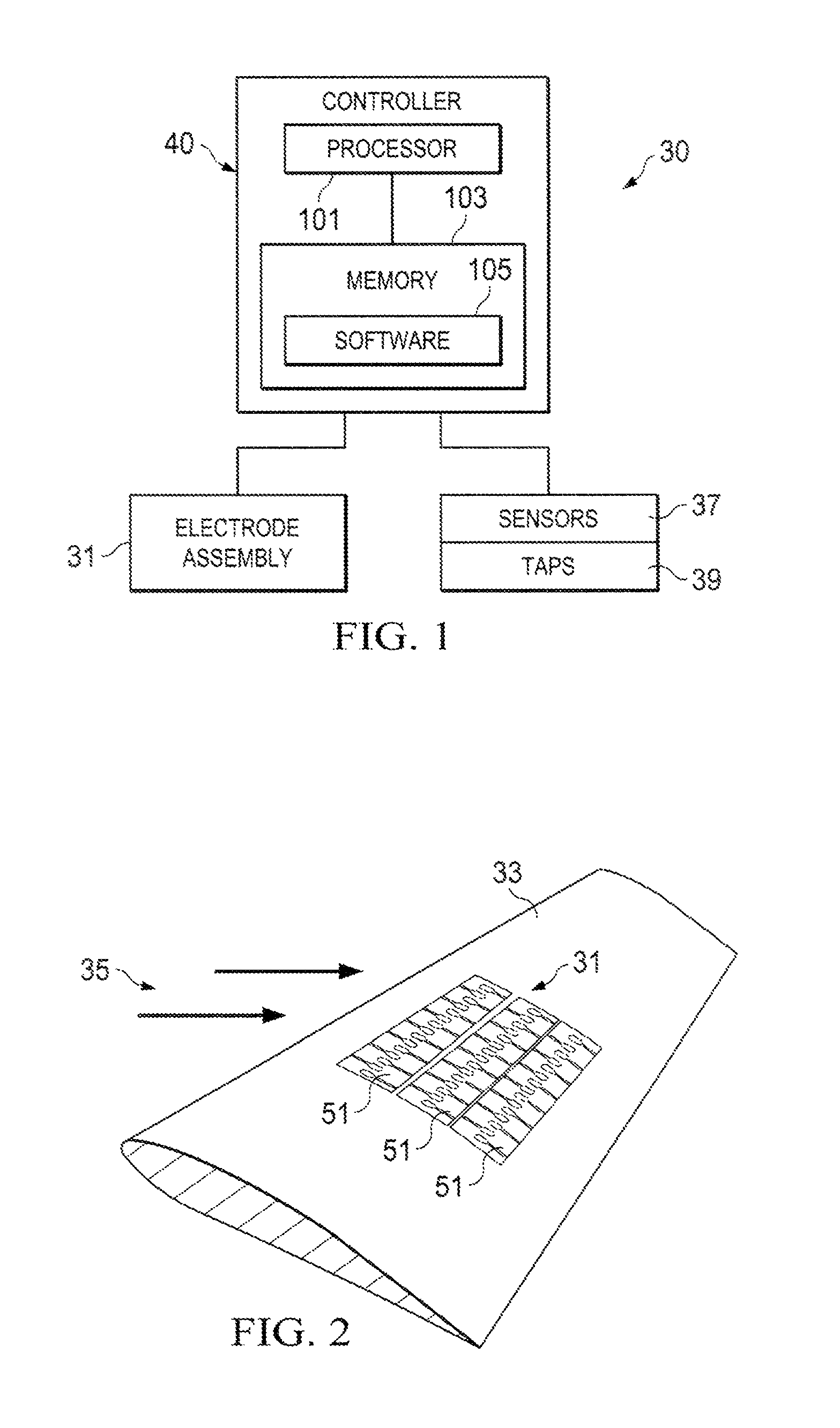
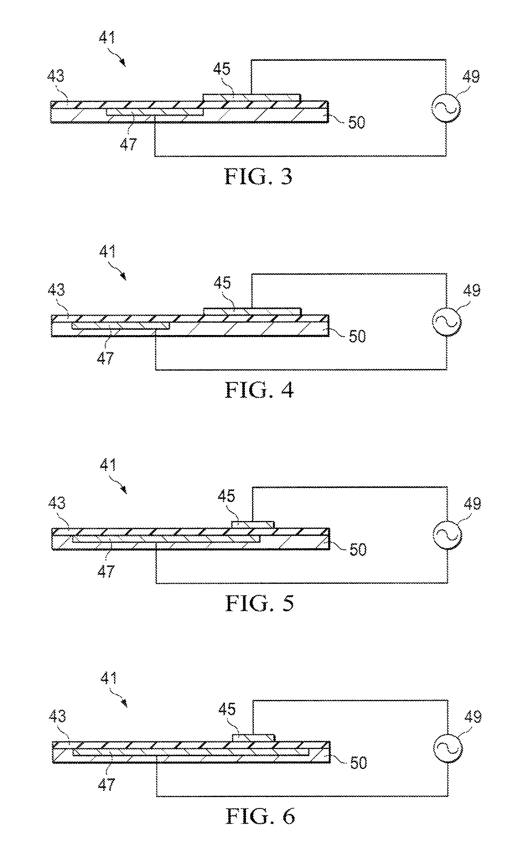
[0054]Various embodiments of the present invention beneficially provide flow control systems, apparatus, devices, electrode assemblies, controllers, program product, and methods for controlling boundary layer flow across an aerodynamic structure, which can produce separate regions of flow structures at different strengths by means of dielectric-barrier-discharge (DBD) type plas...


PUM


Abstract

Systems, apparatus, and program product and methods for controlling boundary layer flow across an aerodynamic structure which can produce separate regions of flow structures at different strengths by means of dielectric-barrier-discharge (DBD) type plasmas, are provided. An example of such apparatus provides plasma regions that are capable of being individually controlled by voltage and / or frequency, and modulated for the purposes of flow control. The apparatus includes an electrode assembly fitted with electrodes on either side of a dielectric such that different electrode geometries and arrangements create isolated regions of plasmas which results in separate regions of flow structures. These regions may be further controlled and modulated by the use of electronic-switching to produce irregularly shaped flow structures and strengths including those having a primarily vertical component.

Description

BACKGROUND OF THE INVENTION[0001]1. Field of the Invention[0002]The present invention relates generally to flow field management. More specifically, the present invention relates to systems, apparatus, program product, and methods for providing boundary layer flow control by the creation of separated flow structures using plasma actuators employing dielectric barrier discharge principles.[0003]2. Description of the Related Art[0004]Adverse fluid flows generated over aerodynamic surfaces can buffet and fatigue any downstream structures so exposed. Additionally, such flows can affect efficiency by increasing drag or resistance over the surface. Such adverse fluid flows can be generated at the fore body of an aircraft or other upstream structure, and damage control surfaces, engines, after body or empennage, nacelles, turrets, or other structures integrated into the airframe. Additionally, these adverse fluid flows can be ingested within engine air intakes or other like air inlets lead...

Claims


Application Information

Patent Timeline
Patent Type & Authority Patents(United States)
IPC IPC(8): B64C23/00
CPCB64C23/005Y02T50/166Y02T50/10
Inventor ESSENHIGH, KATHERINE ANNETAO, FENGFENGBENNETT, GROVER ANDREWBOESPFLUG, MATTHEWMURRAY, ROBERT C.SADDOUGHI, SEYED GHOLANI
Owner LOCKHEED MARTIN CORP
Learn More