Optical logic gate

a logic gate and optical technology, applied in logic circuits, pulse techniques, instruments, etc., can solve the problems of inability to achieve ideal fronts of electrical signals, and inability to accurately describe logic gates

Active Publication Date: 2013-08-27
SELEX SISTEMI INTEGRATI
View PDF2 Cites 2 Cited by
  • Summary
  • Abstract
  • Description
  • Claims
  • Application Information

AI Technical Summary

Benefits of technology

[0009]The object of the present invention is to provide an optical logic gate that allows the above-indicated drawbacks of known art to be at least partially overcome.

Problems solved by technology

At the electrical level, the description of the logic gates becomes complicated, as each logic gate, which is physically embodied by means of an electronic circuit, introduces propagation delays and reacts to changes in the logic state at its inputs in a non-ideal manner.
In addition, the fronts of the electrical signals are never ideal, i.e. they do not provide instantaneous switching of the electrical characteristic from the first to the second value, but rather exhibit a transition period in which the electrical characteristic assumes intermediate values and in which the behaviour of the logic gate is undetermined.
Lastly, electrical signals are inevitably affected by noise, with consequent performance degradation of the logic gate.

Method used


Image

  • Optical logic gate
  • Optical logic gate
  • Optical logic gate

Examples


Embodiment Construction

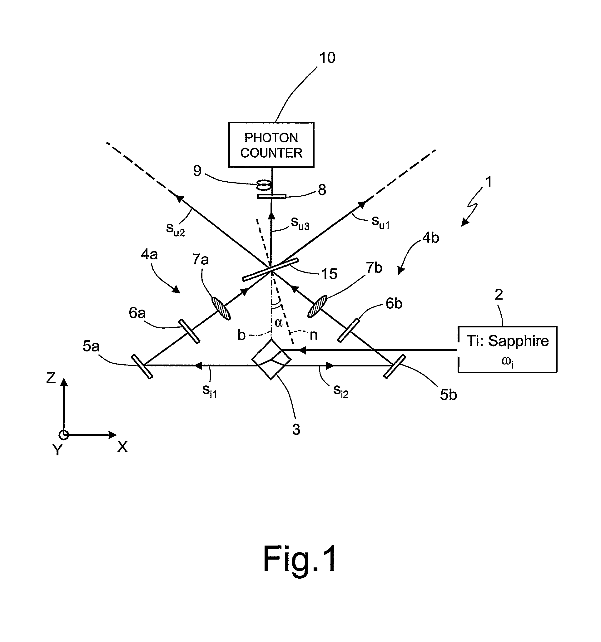
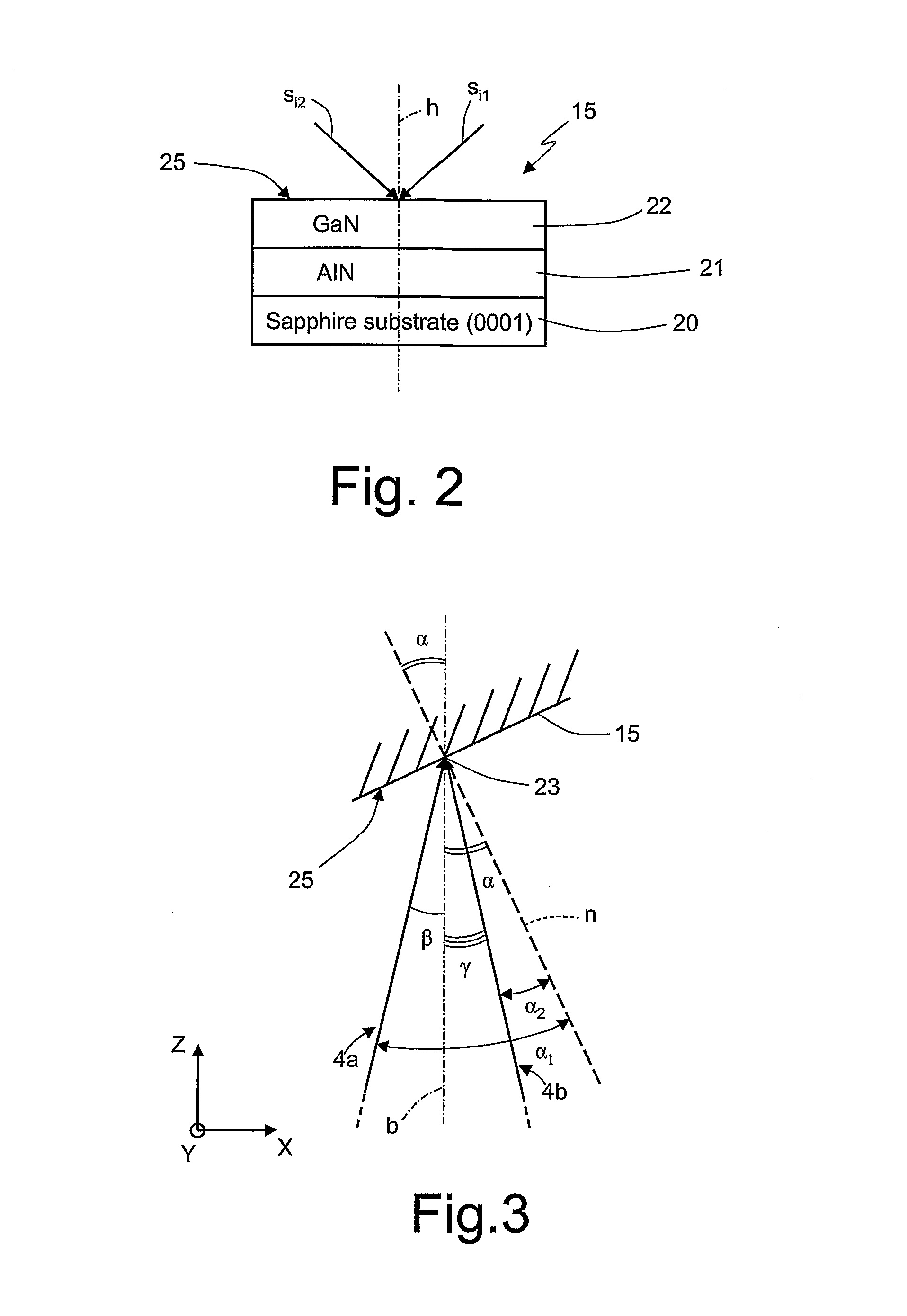
[0016]As shown in FIG. 1, this optical logic gate 1 comprises:[0017]an optical source 2, adapted to generate quasi-monochromatic electromagnetic radiation with angular frequency ωi,[0018]a beam splitter 3, having a shape and arrangement with respect to the optical source 2 such that it is adapted to receive the quasi-monochromatic electromagnetic radiation in input and consequently generate a first and a second optical pump signal si1 and si2 in output having angular frequency ωi, directing them to a first and a second optical path 4a and 4b respectively,[0019]a first and a second reflective surface 5a and 5b, respectively arranged along the first and the second optical paths 4a and 4b, so as to receive the optical pump signals si1 and si2 generated by the beam splitter3,[0020]a first and a second polarizing plate 6a and 6b of the half-wave type, respectively arranged along the first and second optical paths 4a and 4b, downstream of the reflective surfaces 5a and 5b, so as to receiv...


PUM

PropertyMeasurementUnit
angleaaaaaaaaaa
wavelengthaaaaaaaaaa
thicknessaaaaaaaaaa

Abstract

Optical logic gate having a second-harmonic generator element that receives a first and a second optical input signal respectively having a first and a second angular frequency and respectively having a first and a second polarization, and which provides a second-harmonic optical signal having a third angular frequency and a third polarization. The third angular frequency is equal to the sum of the first and the second angular frequency. The third polarization is a function of the first and the second polarization. The second-harmonic generator element includes a second-harmonic generator layer in a material having a non-null second-order optical tensor.

Description

CROSS-REFERENCE TO RELATED APPLICATIONS[0001]This is the U.S. national phase application of International Application No. PCT / IT2008 / 000724, filed Nov. 24, 2008.TECHNICAL FIELD[0002]The present invention concerns an optical logic gate. In particular, the present invention concerns an optical logic gate of the “exclusive-OR” (EXOR) or “exclusive-NOR” (EXNOR) type.BACKGROUND ART[0003]As is known, electronic circuits that implement logical (Boolean) operations, i.e. operations involving logic states, have been available for a long time, these electronic circuits being known as logic gates. The NOT, AND, OR, XOR, NOR, NAND and XNOR operations are some of the logic operations performed by the more common logic gates.[0004]A logic gate comprises one or more inputs able to receive respective electrical input signals, and one or more electrical outputs able to provide respective electrical output signals. Both the electrical input signals and the electrical output signals are typically digi...

Claims


Application Information

Patent Timeline
Patent Type & Authority Patents(United States)
IPC IPC(8): G02F3/00
CPCG02F3/00G02F1/37G02F1/3534G02F2202/10
Inventor BOVINO, FABIO ANTONIOGIARDINA, MAURIZIOLARCIPRETE, MARIA CRISTINACENTINI, MARCOBELARDINI, ALESSANDROSIBILIA, CONCITABERTOLOTTI, MARIOPASSASEO, ADRIANATASCO, VITTORIANNACINGOLANI, ROBERTO
Owner SELEX SISTEMI INTEGRATI
Why Eureka
Try Eureka