
Single-photon generation apparatus and quantum bit reading apparatus and method

a generation apparatus and quantum bit technology, applied in the field of single-photon generation apparatus and quantum bit reading apparatus and method, can solve the problems of no method of ejecting photons in a particular, a lot of time, and light becomes stray light (noise) and is liable to mix with a single photon to be used

Inactive Publication Date: 2009-04-02
KK TOSHIBA
View PDF3 Cites 26 Cited by
  • Summary
  • Abstract
  • Description
  • Claims
  • Application Information

AI Technical Summary

Benefits of technology

[0013]In accordance with an aspect of the invention, there is provided a method of generating a single photon, comprising: preparing an optical resonator having a resonator mode of a resonance angular frequency ωc; preparing a material contained in the optical resonator, having a low energy state |g> and a high energy state |e>, and having a transition angular frequency ωa between |g>−|e> that is varied by an external field; applying, to the material, light of an angula...

Problems solved by technology

In this method, however, the angular frequency (wavelength) of strongly excited light is equal to an angular frequency (wavelength) corresponding to the resonator mode, and the light becomes stray light (noise) and is liable to mix with a single photon to be used.
However, in these methods, at least a period of approx.
Also in this case, light of the same frequency as that of the resonator mode is applied, which inevitably causes the same problem as in the case of using the two-state system.
In this method, however, photons are ejected in various modes (directions), and no method of ejecting photons in a particular mode is disclosed.
A simple method of ejecting a single photon is not known, which differs from the conventional methods requiring a lot of time, or being complex and requiring a restoration process wherein stray light may be intensified, and which can realize a repetition frequency of approx. g / π, and in which excitation light differs in frequency (wavelength) from a resonator mode, i.e., a photon ejected.

Method used


Image

  • Single-photon generation apparatus and quantum bit reading apparatus and method
  • Single-photon generation apparatus and quantum bit reading apparatus and method
  • Single-photon generation apparatus and quantum bit reading apparatus and method

Examples


first example

[0072]FIG. 9 shows a single-photon generation apparatus according to first to fourth examples. In the first example, Rabi oscillation is used in the first stage, and vacuum Rabi oscillation is used in the second stage.

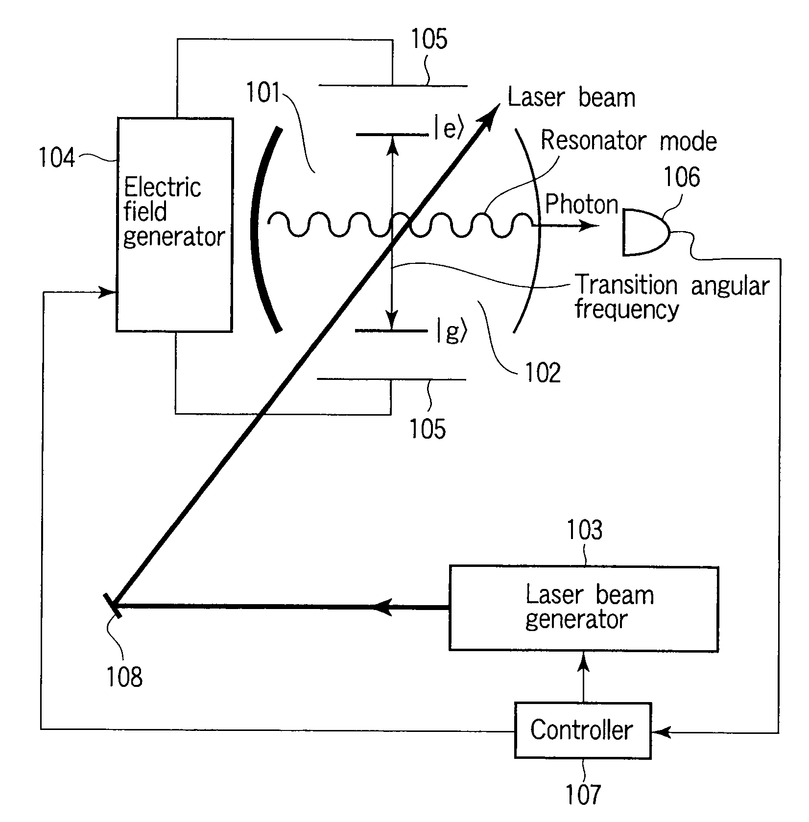
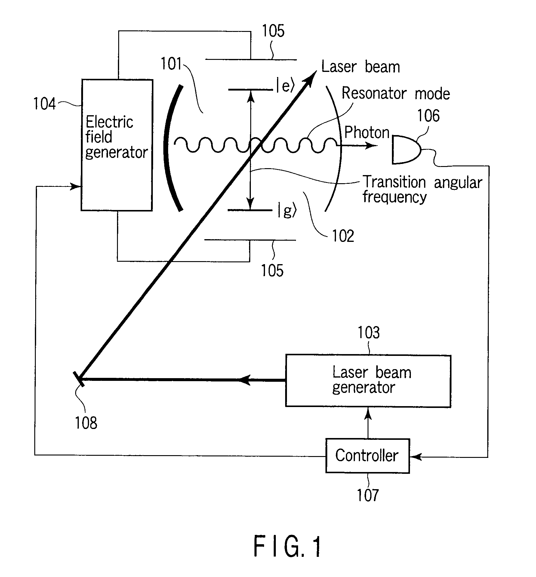
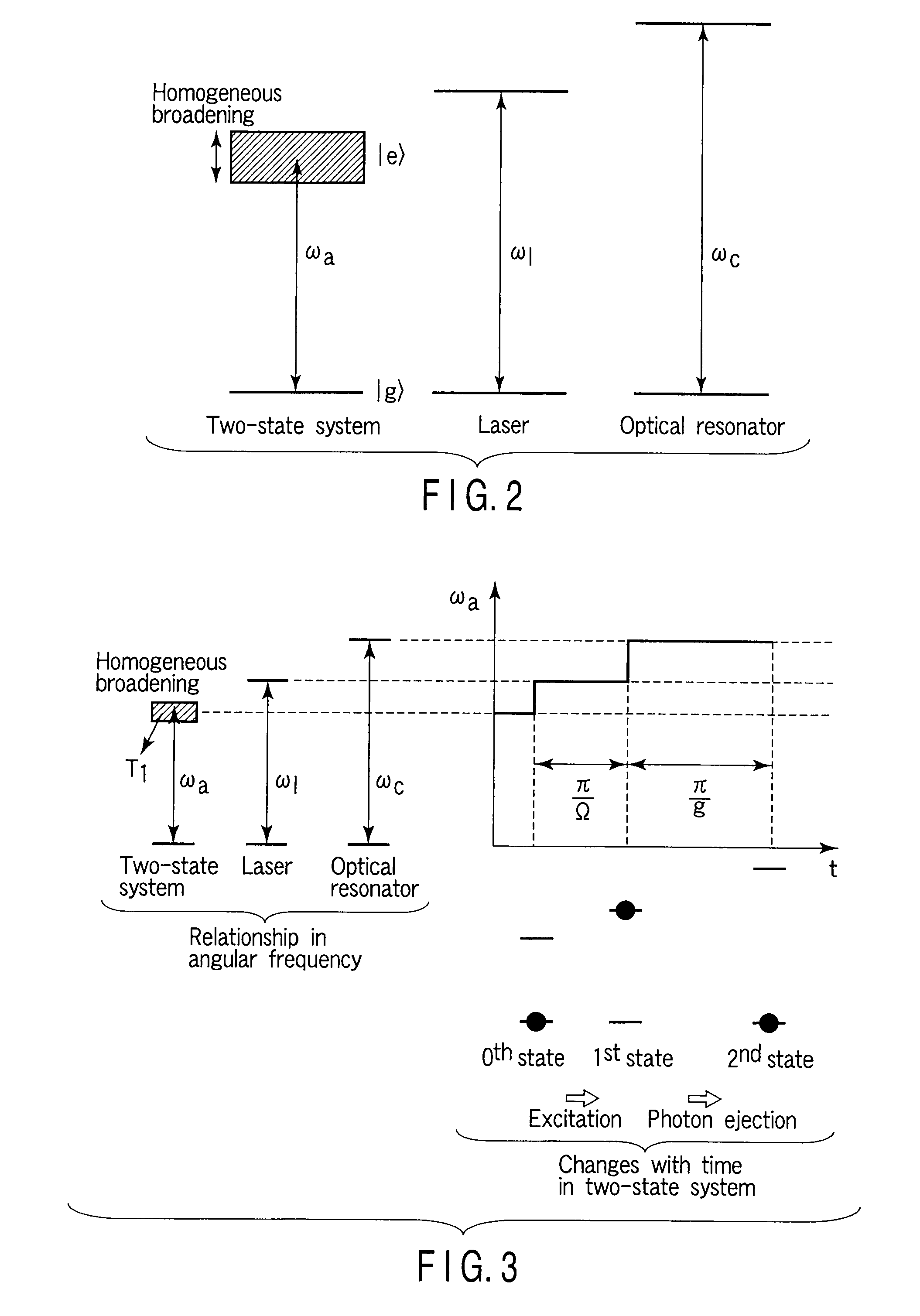
[0073]In the single-photon generation apparatus of the first example and a method employed therein, a Pr3+ ion contained in Pr3+:Y2SiO5 crystal obtained by replacing 10−5% Y3+ ions in Y2SiO5 crystal with Pr3+ ions is used as a two-state system. The Pr3+:Y2SiO5 crystal corresponds to the material 102. This crystal has a size of approx. 2 mm×2 mm×2 mm, and extra-high reflectance mirrors are formed on the opposite surfaces of the crystal to have a resonator structure. One of the mirrors is set to a reflectance of substantially 100% (99.998% or more), and the other mirror is set to a reflectance of 99.924%, thereby providing a one-sided resonator (corresponding to the optical resonator 101). The resonator mode of this resonator is made to resonate with a frequency higher b...

second example

[0081]In a second example, adiabatic passage is used in both the first and second stages.

[0082]In the second example, when applying an electric field to crystal containing a Pr3+ ion, the controller 903 firstly applies the electric field E(1) to the crystal, to which any electric field is not yet applied, then increases the electric field E(1) to the electric field E(3) at a preset increase rate in 10 μs, then increases the electric field E(3) to the electric field E(4), and then increases the electric field E(4) to the electric field E(6) at a preset increase rate in 40 μs. Thereafter, the controller 903 restores the state of the crystal to the initial state in which no electric field is applied, and then resumes the above-mentioned electric field application and increase. By repeating this process, a photon is ejected, every approx. 50 μs, to the low-reflectance mirror side of the optical resonator 101 as a one-sided resonator. This operation can be observed by the photodetector 1...

third example

[0083]In a third example, Rabi oscillation is used in the first stage, and adiabatic passage is used in the second stage.

[0084]In the third example, when applying an electric field to crystal containing a Pr3+ ion, the controller 903 firstly applies, for 1 μs corresponding to π / Ω, the electric field E(2) to the crystal, to which any electric field is not yet applied, then increases the electric field E(2) to the electric field E(4), and then increases the electric field E(4) to the electric field E(6) at a preset increase rate in 40 μs. Thereafter, the controller 903 restores the state of the crystal to the initial state in which no electric field is applied, and then resumes the above-mentioned increases in the magnitude of the electric field. By repeating this process, a photon is ejected, every approx. 40 μs, to the low-reflectance mirror side of the optical resonator 101 as a one-sided resonator.

[0085]This operation can be observed by the photodetector 106.


PUM


Abstract

A method of generating a single photon, includes preparing an optical resonator including a resonator mode of a resonance angular frequency ωc, preparing a material contained in the optical resonator, including a low energy state |g> and a high energy state |e>, and including a transition angular frequency ωa between |g>−|e> that is varied by an external field, applying, to the material, light of an angular frequency ωl different from the resonance angular frequency ωc, and applying a first external field to the material to vary the transition angular frequency ωa to resonate with the angular frequency ωl, such that a state of the material is changed to |e>, and then applying a second external field to the material to vary the transition angular frequency ωa to resonate with the resonance angular frequency ωc, such that the state of the material is restored to |g>.

Description

CROSS-REFERENCE TO RELATED APPLICATIONS[0001]This application is based upon and claims the benefit of priority from prior Japanese Patent Application No. 2007-250457, filed Sep. 27, 2007, the entire contents of which are incorporated herein by reference.BACKGROUND OF THE INVENTION[0002]1. Field of the Invention[0003]The present invention relates to an easy-to-use single-photon generation apparatus for generating a single photon, and a quantum bit reading apparatus and method.[0004]2. Description of the Related Art[0005]A single-photon source is an important apparatus for quantum information processing techniques, such as quantum computers utilizing a photon, or quantum encryption techniques, and is required to eject a single photon at desired timing in a particular spatial mode.[0006]There is a method for most simply and reliably satisfying the requirement, in which in principle, a π-pulse (π: circular constant) laser is used to excite a two-state system, such as a single atom, ion,...

Claims


Application Information

Patent Timeline
IPC IPC(8): G21G4/00G06N99/00
CPCG06N99/002B82Y10/00G06N10/00
Inventor ICHIMURA, KOUICHIGOTO, HAYATO
Owner KK TOSHIBA
Learn More