
Temperature estimation and tissue detection of an ultrasonic dissector from frequency response monitoring

a tissue detection and ultrasonic dissector technology, applied in the field of ultrasonic surgical instruments, can solve problems such as limitations to the field of view

Active Publication Date: 2020-06-09
COVIDIEN LP
View PDF41 Cites 261 Cited by
  • Summary
  • Abstract
  • Description
  • Claims
  • Application Information

AI Technical Summary

Benefits of technology

The patent text addresses the need for better ways to detect the temperature and type of tissue when using ultrasonic surgical instruments.

Problems solved by technology

However, thermocouples require separate attachment to the ultrasonic surgical instrument, which can present problems.
Current systems for identifying tissue rely on either high cost scanning mechanisms including ultrasound, CAT, and MRI, or lower cost, but limited to field of view, methods such as optical imaging through a laparoscope.

Method used


Image

  • Temperature estimation and tissue detection of an ultrasonic dissector from frequency response monitoring
  • Temperature estimation and tissue detection of an ultrasonic dissector from frequency response monitoring
  • Temperature estimation and tissue detection of an ultrasonic dissector from frequency response monitoring

Examples


Embodiment Construction

[0032]Particular embodiments of the present disclosure are described herein below with reference to the accompanying drawings. In the following description, well-known functions or constructions are not described in detail to avoid obscuring the present disclosure in unnecessary detail.

[0033]It is to be understood that the disclosed embodiments are merely exemplary of the disclosure, which can be embodied in various forms. Therefore, specific structural and functional details disclosed herein are not to be interpreted as limiting, but merely as a basis for the claims and as a representative basis for teaching one skilled in the art to variously employ the present disclosure in virtually any appropriately detailed structure. Further, the terms and phrases used herein are not intended to be limiting; but rather, to provide an understandable description of the disclosure.

[0034]Before the present disclosure is disclosed and described, it is to be understood that the terminology used her...


PUM


Abstract

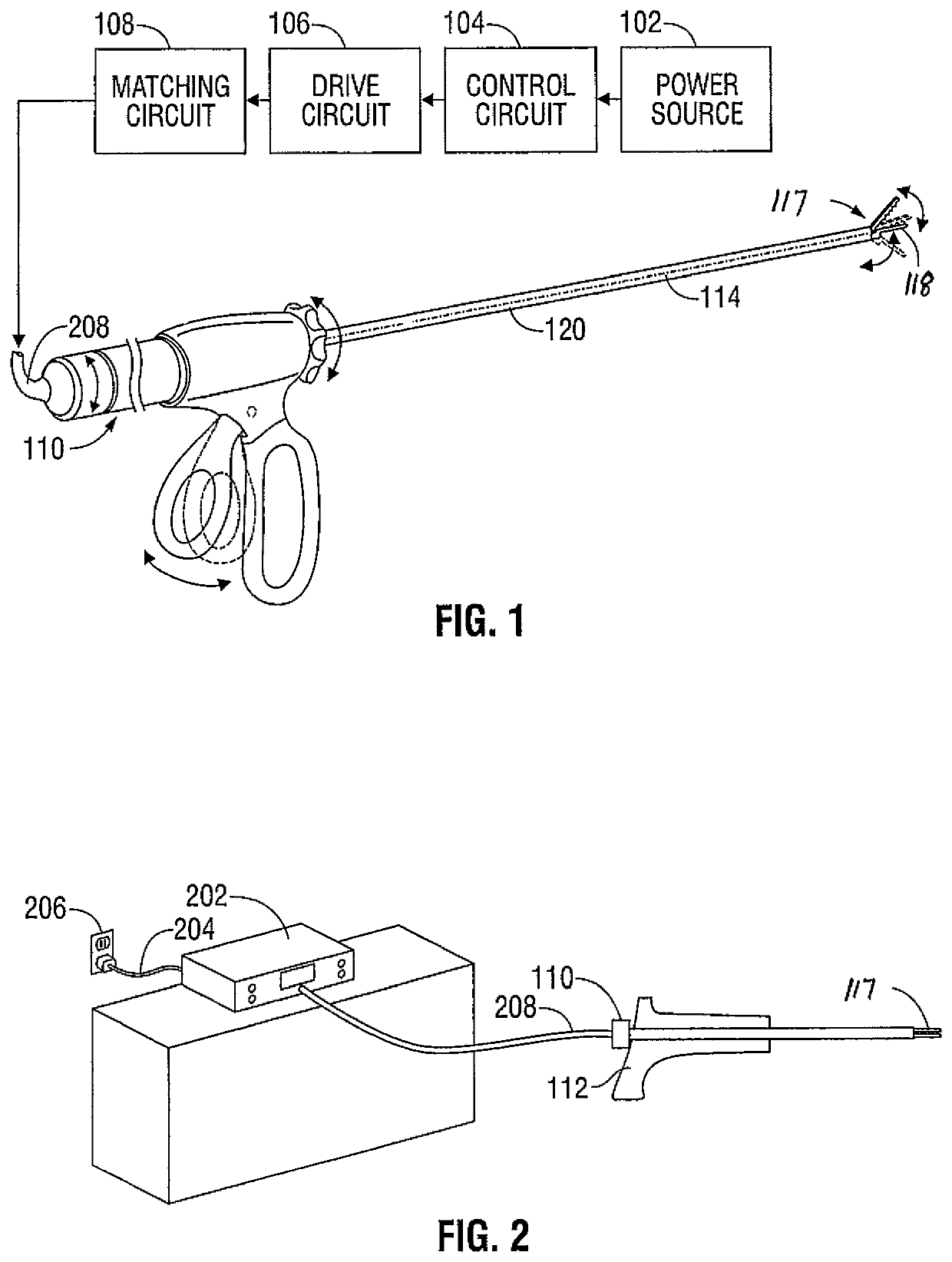
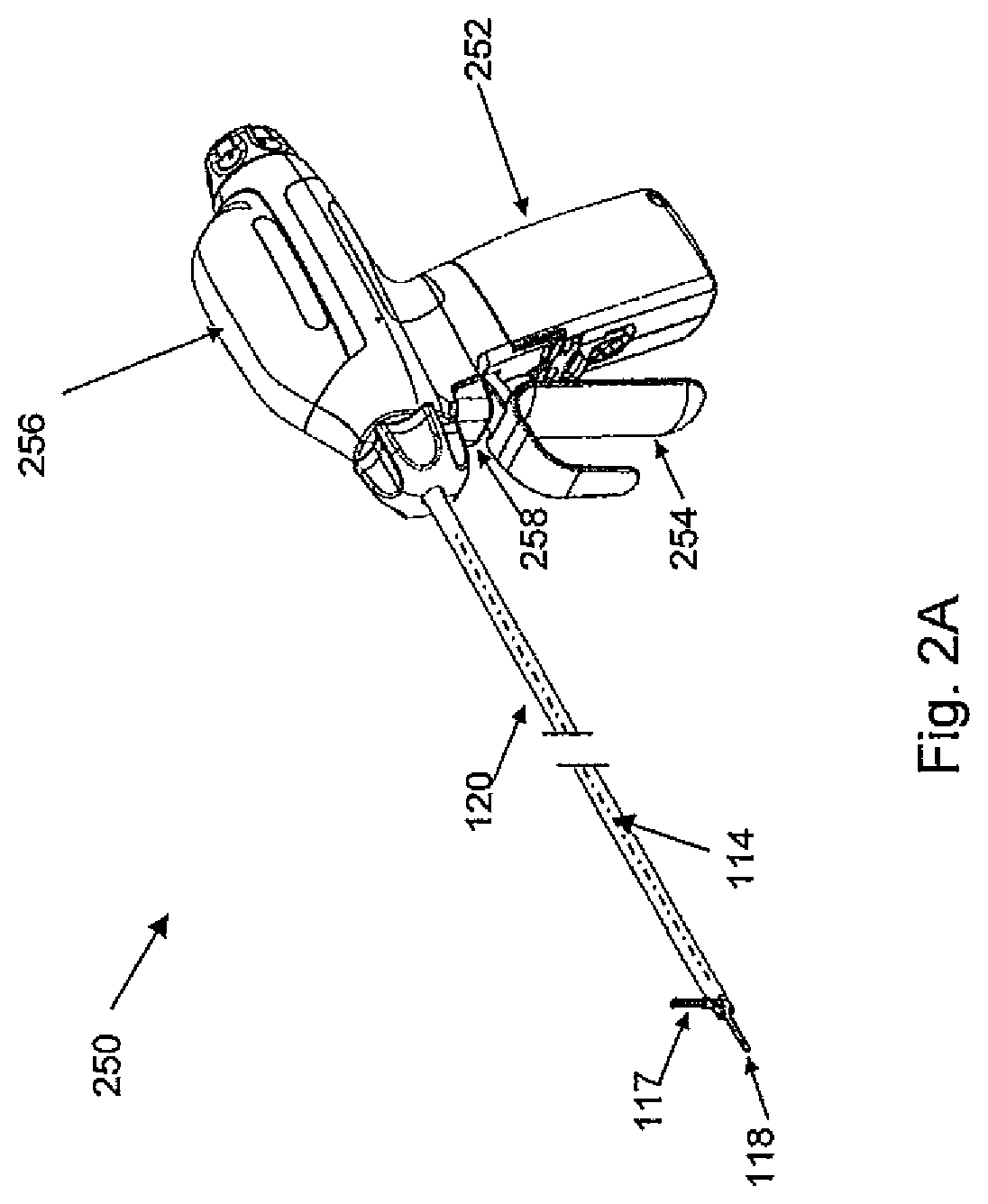
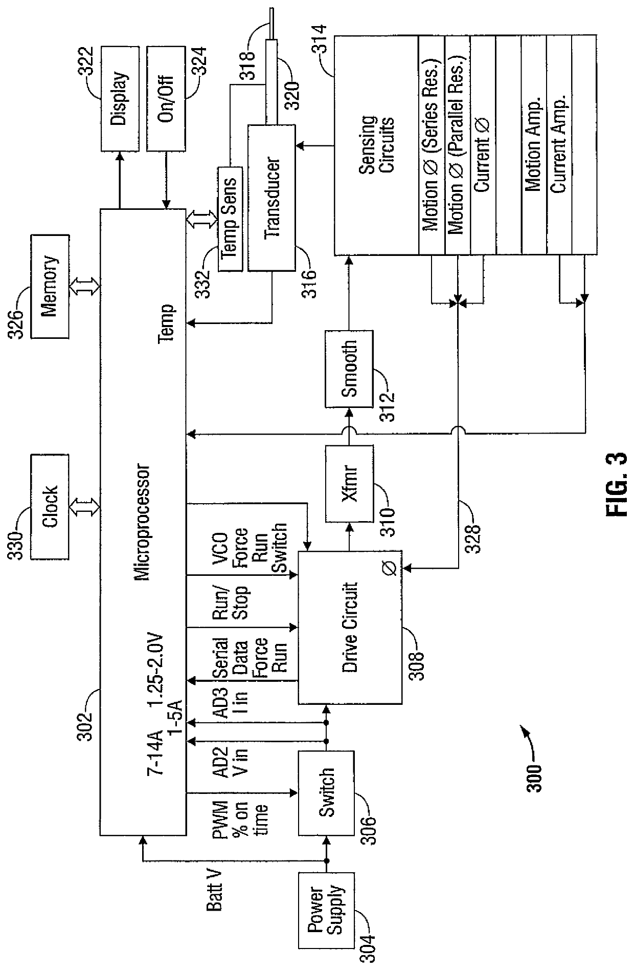
An ultrasonic surgical apparatus and method, the apparatus including a signal generator outputting a drive signal having a frequency, an oscillating structure, receiving the drive signal and oscillating at the frequency of the drive signal, and a bridge circuit, detecting the mechanical motion of the oscillating structure and outputting a signal representative of the mechanical motion. The ultrasonic surgical apparatus also includes a microcontroller receiving the signal output by the bridge circuit, the microcontroller determining an instantaneous frequency at which the oscillating structure is oscillating based on the received signal, and determining a frequency adjustment necessary to maintain the oscillating structure oscillating at its resonance frequency, the microcontroller further determining the quality (Q value) of the signal received from the bridge circuit and determining material type contacting the oscillating structure.

Description

CROSS REFERENCE TO RELATED APPLICATIONS[0001]This application claims the benefit of U.S. Provisional Patent Application Ser. No. 61 / 658,067 filed Jun. 11, 2012; U.S. Provisional Patent Application Ser. No. 61 / 658,045 filed Jun. 11, 2012; and U.S. Provisional Patent Application Ser. No. 61 / 658,081 filed Jun. 11, 2012. The entire contents of these cross-referenced applications are incorporated by reference herein.BACKGROUND1. Technical Field[0002]The present disclosure relates generally to an ultrasonic surgical instrument and, more particularly, relates to estimating the temperature of the ultrasonic surgical instrument and distinguishing the type of tissue engaged by the ultrasonic surgical instrument.2. Background of the Related Art[0003]Ultrasonic instruments are effectively used in the treatment of many medical conditions, such as removal of tissue and the cauterization and sealing of vessels. Cutting instruments that utilize ultrasonic waves generate vibrations with an ultrasoni...

Claims


Application Information

Patent Timeline
Patent Type & Authority Patents(United States)
IPC IPC(8): G01N29/44A61B17/32A61B17/00
CPCG01N29/44A61B17/320092A61B2017/320095A61B2017/00106A61B2017/0003A61B2017/320094A61B2017/00084A61B2017/00734A61B2017/00075
Inventor ROSS, ANTHONY B.VAN TOL, DAVID J.PRICE, DAVID
Owner COVIDIEN LP
Learn More