
Voltage regulation of a virtual power rail

a virtual power rail and voltage regulation technology, applied in the field of logic circuitry, can solve the problems of data loss risk and increased wake up times, and achieve the effects of reducing voltage levels, reducing power loss, and increasing wake up times

Active Publication Date: 2013-08-27
ARM LTD
View PDF5 Cites 17 Cited by
  • Summary
  • Abstract
  • Description
  • Claims
  • Application Information

AI Technical Summary

Benefits of technology

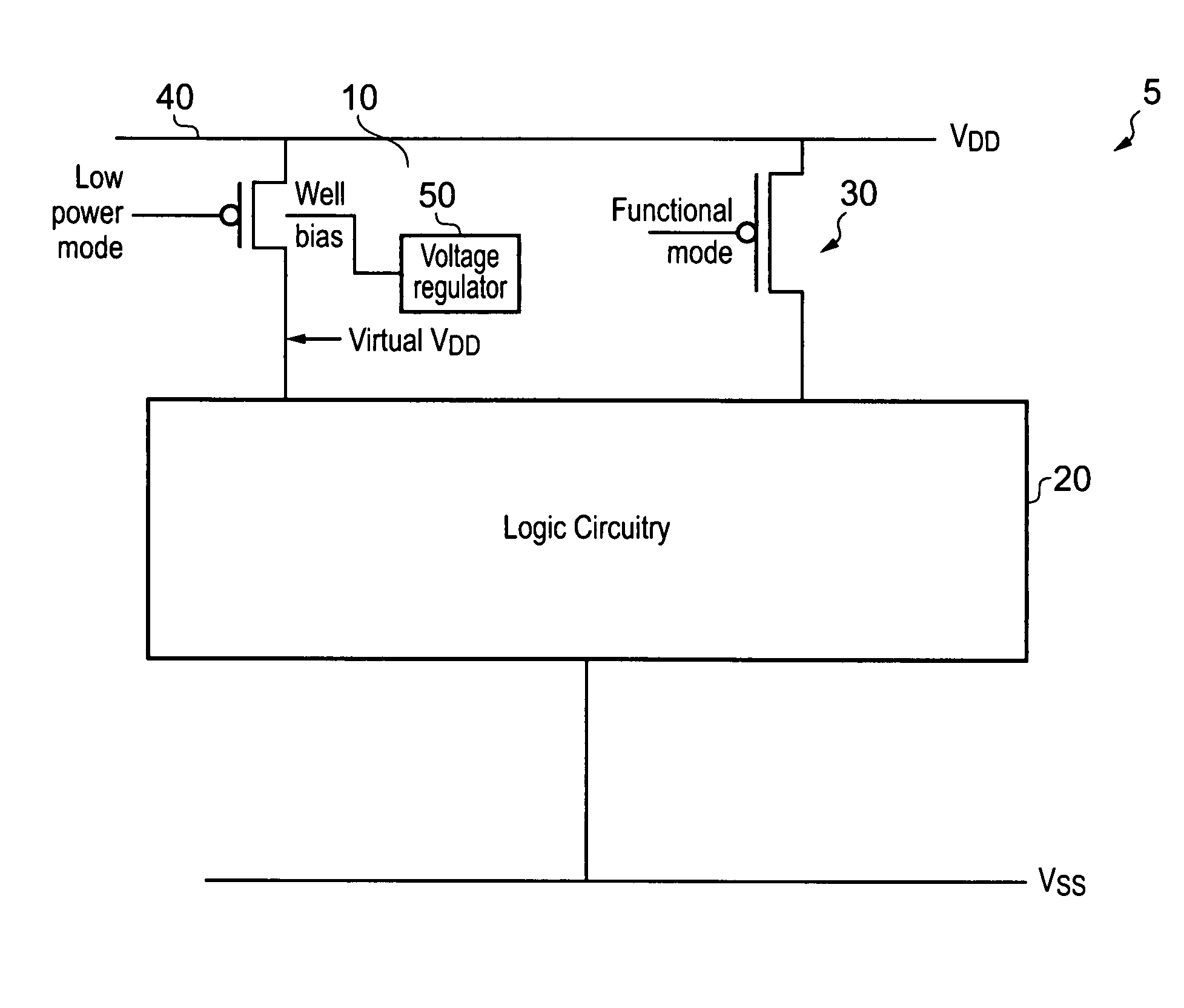
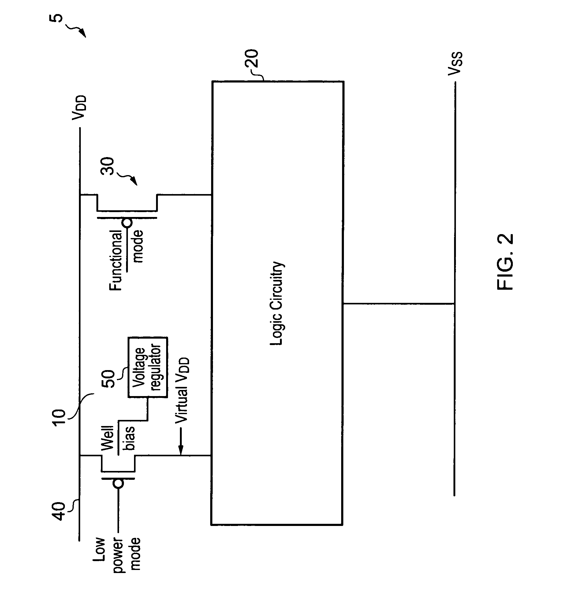
The present invention is about a way to reduce power consumption in logic circuitry by using a low power data retention mode where the circuitry only needs to maintain current state and not process data. This mode requires less power than the normal functional mode but it also carries the risk of data loss. To address this, the invention provides a way of regulating the voltage levels applied to the logic circuitry in a fine level of control, allowing a desired voltage level to be selected and maintained accurately. The leakage power controller can adjust the virtual rail voltage level by varying the well bias not only to manage power savings but also to avoid data loss. The invention includes a voltage sensor to detect the virtual voltage level and adjust the well bias voltage accordingly. The logic circuitry may be made up of weak transistors that operate in their saturation region, and the saturation current can be adjusted by varying the well bias voltage. This results in a transistor that acts almost like a constant current source, and the current through the transistor depends on the well bias voltage. This approach helps to achieve accurate voltage control while reducing power consumption.

Problems solved by technology

However, reducing voltage levels too far carries the risk of data loss and increased wake up times.

Method used


Image

  • Voltage regulation of a virtual power rail
  • Voltage regulation of a virtual power rail
  • Voltage regulation of a virtual power rail

Examples


Embodiment Construction

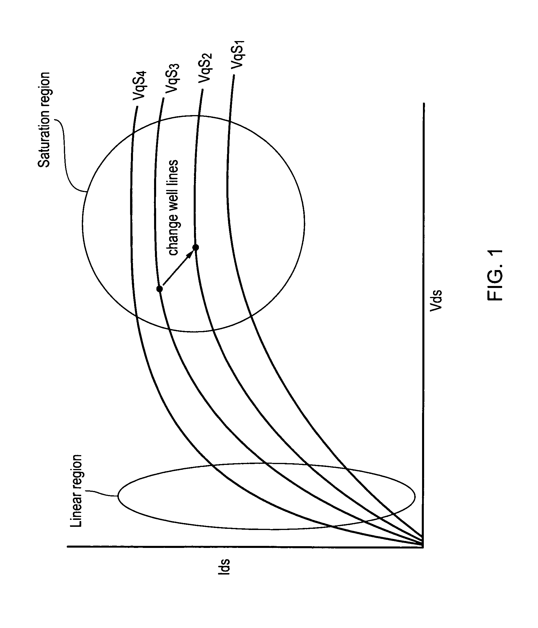
[0051]FIG. 1 shows a graph illustrating how the current through a transistor varies with the voltage across it at different gate voltages. As can be seen when a transistor is in conducting mode, it operates at first in a linear region where an increase in voltage across the transistor produces a corresponding increase in current. At a certain point it reaches a saturation mode, where it cannot conduct any more current and thus, as the voltage across the transistor changes it continues to output approximately the same current. In this regard although the current is almost constant there is a slight slope which is referred to as channel length modulation, however, it is negligible when compared to the rate of change of current when operating in the linear region. This saturation current varies with Vgs which is the voltage level at the source Vs minus the voltage level at the gate Vg minus the threshold voltage Vth of the transistor. Thus, changing the threshold voltage of the transis...


PUM


Abstract

A voltage regulator for regulating a voltage level of a virtual power rail supplying power to logic circuitry in a low power data retention mode is disclosed. The voltage regulator comprises: switching circuitry having a transistor for coupling said virtual power rail to a power supply having a supply voltage level; control circuitry responsive to a signal indicating the logic circuitry is to enter the low data power retention mode to control the switching circuitry to switch to a conductive state in which the transistor is operating in a saturation region of operation and supplying a saturation current from the power supply via the virtual power rail to the logic circuitry; and a leakage power controller for adjusting a voltage level of the virtual power rail to control leakage power. The leakage power controller is configured to supply a bias voltage to the well in which the switching circuitry is formed, the saturation current of the switching circuitry being dependent on a value of the well bias voltage. The leakage power controller is configured to adjust the well bias voltage of the switching circuitry thereby varying the saturation current and the voltage level of the virtual power rail.

Description

BACKGROUND OF THE INVENTION[0001]1. Field of the Invention[0002]The field of the invention relates to the field of logic circuitry and in particular to the supply of power to logic circuitry in both functional and low power data retention modes.[0003]2. Description of the Prior Art[0004]It is known to provide power to logic circuitry using power rails connected via switch blocks to virtual power rails. The logic circuitry then draws its power from the virtual power rails. The switch blocks, which are typically high threshold voltage header and / or footer transistors, can be used to isolate the virtual power rail from the main power rail and accordingly isolate the logic blocks from the power supply and turn the circuitry off. This is useful in reducing power consumption of the logic circuitry. A problem with this is that state (e.g. data values, instruction values, configuration etc) within the logic circuitry is lost when it is isolated from the power supply. Furthermore, it can tak...

Claims


Application Information

Patent Timeline
Patent Type & Authority Patents(United States)
IPC IPC(8): H03K3/01
CPCH03K19/0013H03K19/0016
Inventor IDGUNJI, SACHIN SATISHSANDHU, BAL S
Owner ARM LTD
Learn More