
Point light source and light source module using the same

a technology of light source module and light source, which is applied in the direction of light source semiconductor devices, lighting and heating apparatus, lighting support devices, etc., can solve the problems of reducing the luminous efficiency of light emitting diodes, requiring reflow process, and affecting the production yield of light source modules of the present invention

Active Publication Date: 2013-08-20
LEXTAR ELECTRONICS CORP
View PDF15 Cites 1 Cited by
  • Summary
  • Abstract
  • Description
  • Claims
  • Application Information

AI Technical Summary

Benefits of technology

The wedging mechanism improves production yield by preventing LED damage and simplifying the replacement process, ensuring efficient connection and assembly of light sources without the need for surface mounted technology.

Problems solved by technology

However, in the surface mounted technology, a reflow process is needed.
The light emitting diodes and the circuit board may be damaged during passing through a reflow oven.
As a result, luminous efficiency of the light emitting diodes is reduced or the light emitting diodes are not available, such that production yield of the light source module is reduced.
Moreover, when the light emitting diodes are damaged, it is difficult and too time consuming to replace new light emitting diodes.

Method used


Image

  • Point light source and light source module using the same
  • Point light source and light source module using the same
  • Point light source and light source module using the same

Examples


Embodiment Construction

[0025]The present invention will now be described more specifically with reference to the following embodiments. It is to be noted that the following descriptions of preferred embodiments of this invention are presented herein for purpose of illustration and description only. It is not intended to be exhaustive or to be limited to the precise form disclosed.

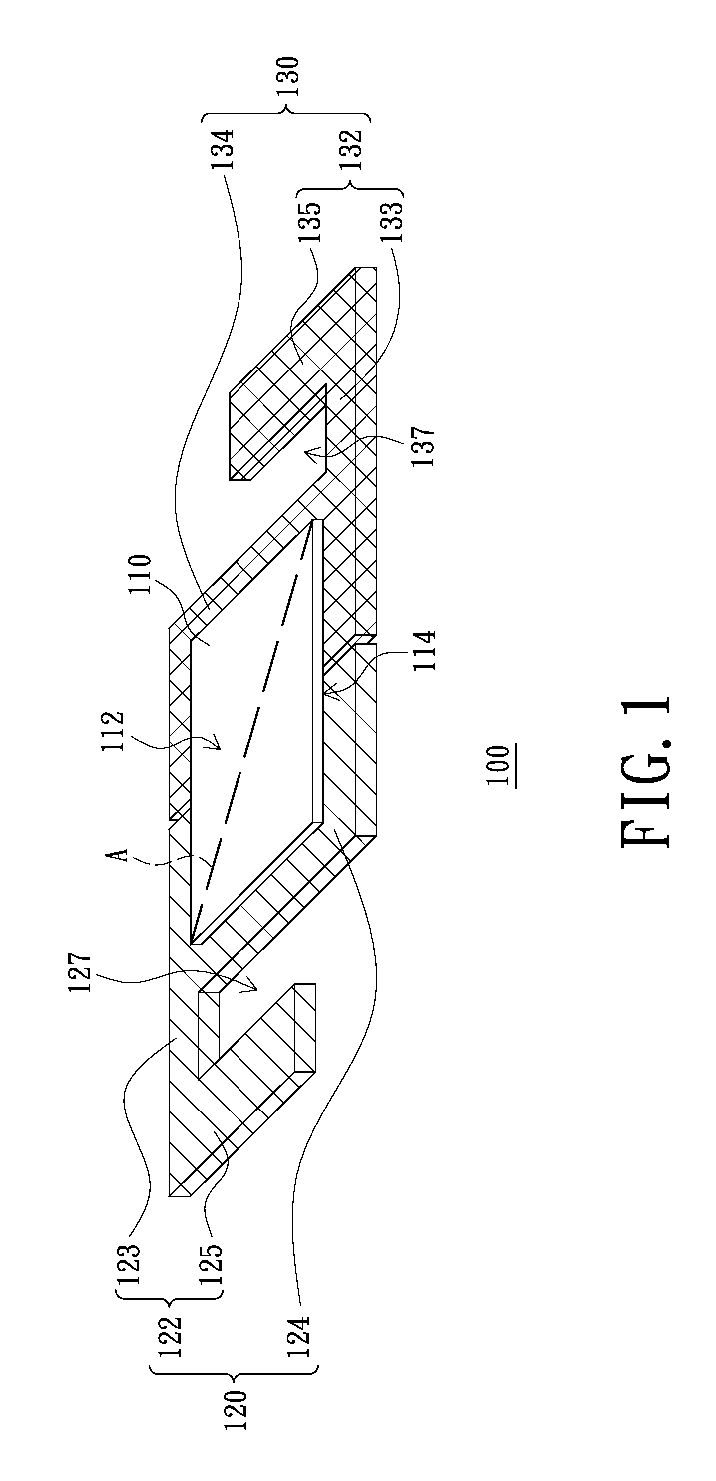
[0026]FIG. 1 is a schematic, three-dimensional view of a point light source according to an embodiment of the present invention. Referring to FIG. 1, a point light source 100 of the present embodiment can be, but not limited to, a light emitting diode or a laser. The point light source 100 includes a light-emitting portion 110, a first lead 120 and a second lead 130. The first lead 120 and the second lead 130 are electrically connected to the light-emitting portion 110. The first lead 120 and the second lead 130 respectively have a wedging portion 122, 132. The wedging portion 122 and the wedging portion 132 can be matched with e...


PUM


Abstract

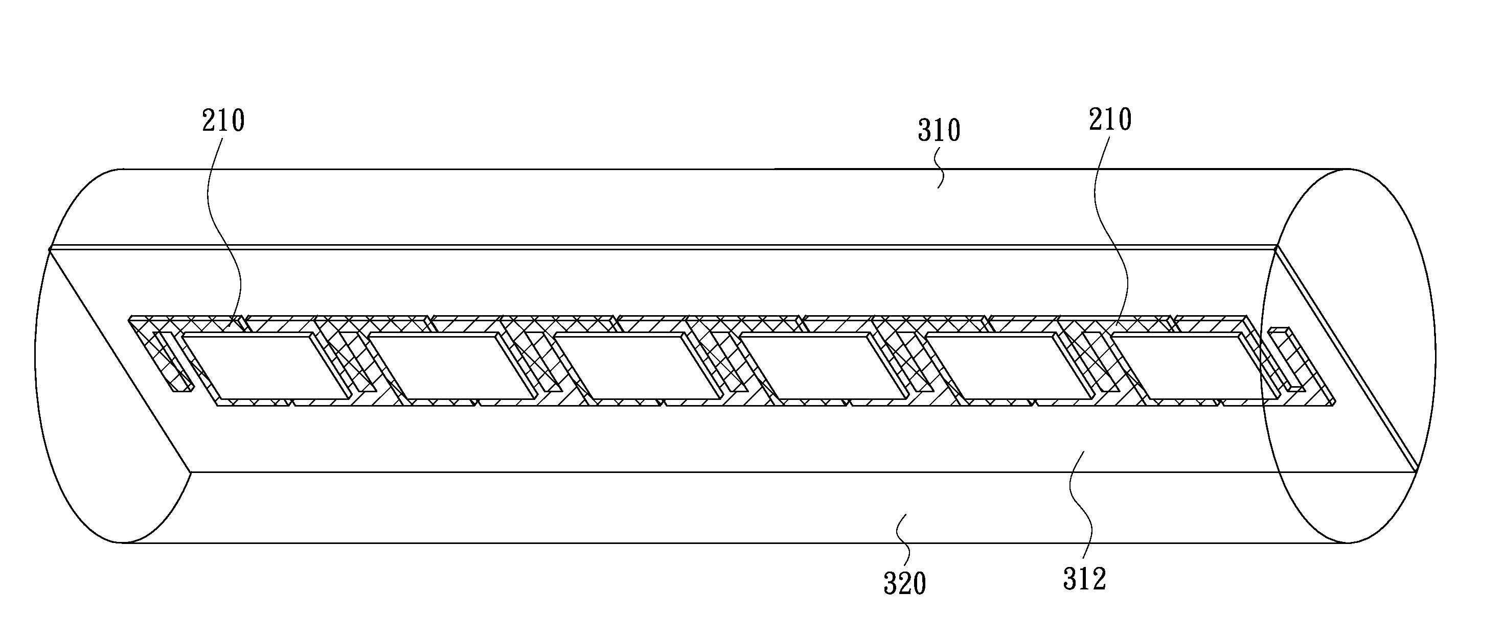
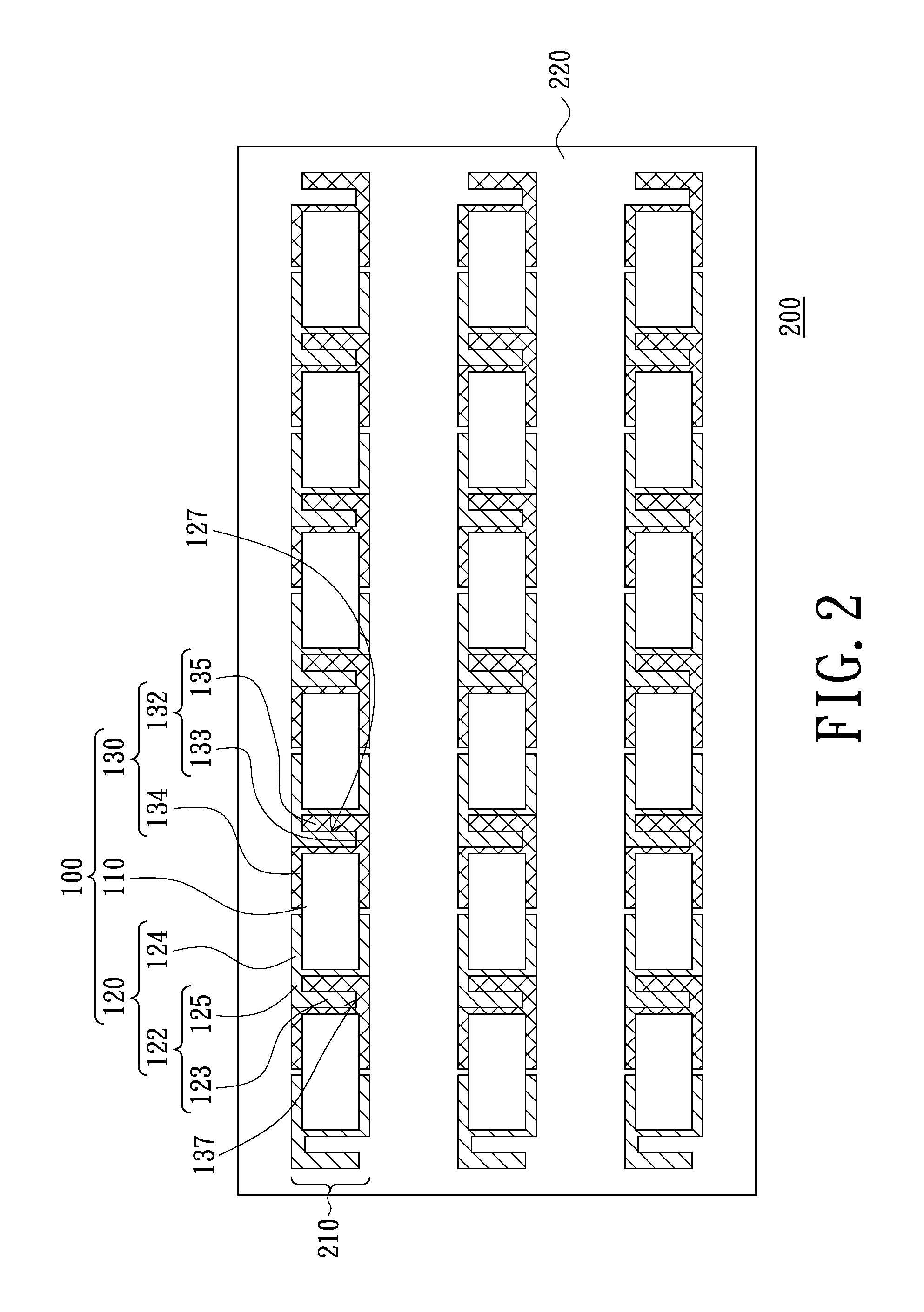
A point light source includes a light-emitting portion, a first lead and a second lead. The first lead and the second lead are electrically connected to the light-emitting portion. The first lead and the second lead respectively have a wedging portion. The wedging portions can be matched with each other. A light source module using the point light source is also provided. The light source module includes at least one light source assembly. Each light source assembly includes a plurality of the point light sources connected in series. Adjacent two point light sources are wedged to each other in series by a combination of the wedging portions of the adjacent first lead and second lead.

Description

FIELD OF THE INVENTION[0001]The present invention relates to a point light source and a light source module using the same, and more particularly to point light sources capable of being wedged to each other and a light source module using the same.BACKGROUND OF THE INVENTION[0002]Since light emitting diodes (LEDs) have advantages of small size, low power consumption, fast response time and long service life, light emitting diodes have been widely used in communication products and consumer electronics in recent years.[0003]In a conventional light source module using light emitting diodes, the light emitting diodes are fixed to a circuit board by surface mounted technology, and leads of the light emitting diodes are electrically connected to the circuit board by soldering tin. However, in the surface mounted technology, a reflow process is needed. The light emitting diodes and the circuit board may be damaged during passing through a reflow oven. As a result, luminous efficiency of t...

Claims


Application Information

Patent Timeline
Patent Type & Authority Patents(United States)
IPC IPC(8): F21V5/00F21S4/00H01L33/62
CPCF21V19/0025F21Y2101/02F21Y2103/003F21S4/003H01L2924/0002H01L33/62H01L2924/00F21S4/20F21Y2103/10F21Y2115/10
Inventor CHEN, CHUN-KUANGSU, CHEN-YI
Owner LEXTAR ELECTRONICS CORP
Learn More