
Charging member and method of producing the member, process cartridge, and electrophotographic image-forming apparatus

a technology of electrophotographic image and process cartridge, which is applied in the direction of electrographic process, instrument, corona discharge, etc., can solve the problems of reducing the size of the electrophotographic image-forming apparatus, disadvantageous to stably and reliably charge the electrophotographic photosensitive member, etc., and achieves the effect of suppressing the adhesion effect of toner or the lik

Active Publication Date: 2013-08-06
CANON KK
View PDF34 Cites 26 Cited by
  • Summary
  • Abstract
  • Description
  • Claims
  • Application Information

AI Technical Summary

Benefits of technology

[0009]In view of the foregoing, the present invention is directed to providing a charging member capable of maintaining, over a long time period, a high charging ability by which a photosensitive member can be stably charged even at a high process speed, and a method of producing the charging member.Further, the present invention is directed to providing an electrophotographic apparatus and a process cartridge capable of stably forming high-quality electrophotographic images.
[0019]According to the present invention, there is provided the charging member excellent in charging performance and whose charging performance hardly changes over time can be obtained. In addition, according to the present invention, provided are the electrophotographic apparatus and the process cartridge capable of stably forming high-quality electrophotographic images can be obtained.

Problems solved by technology

The foregoing is disadvantageous to stably and reliably charge the electrophotographic photosensitive member.
However, the introduction of pre-exposing unit into the electrophotographic image-forming apparatus is disadvantageous for a reduction in size of the electrophotographic image-forming apparatus.

Method used


Image

  • Charging member and method of producing the member, process cartridge, and electrophotographic image-forming apparatus
  • Charging member and method of producing the member, process cartridge, and electrophotographic image-forming apparatus
  • Charging member and method of producing the member, process cartridge, and electrophotographic image-forming apparatus

Examples


example 1

[0135]Materials shown in Table 2 were mixed in a 6-L pressure kneader (the apparatus used here was available under the trade name “TD6-15MDX” from TOSHIN CO., LTD.) at a filling ratio of 70 vol % and a blade speed of 30 rpm for 24 minutes. Thus, an unvulcanized rubber composition was obtained. 4.5 Parts of tetrabenzylthiuram disulfide (trade name: Sanceler TBZTD, manufactured by SANSHIN CHEMICAL INDUSTRY CO., LTD.) as a vulcanization accelerator and 1.2 parts of sulfur as a vulcanizing agent were added to 174 parts by mass of the unvulcanized rubber composition. Then, the mixture was bilaterally cut a total of twenty times with open rolls each having a roll diameter of 30.5 cm (12 inches) at a front roll speed of 8 rpm, a back roll speed of 10 rpm, and a roll interval of 2 mm. After that, the resultant was subjected to tight milling ten times at a roll interval of 0.5 mm. Thus, a kneaded product I for an elastic layer was obtained.

[0136]

TABLE 2Raw materialUsageMedium high acrylonitr...

example 2

A mixture 2 was obtained in the same manner as in Example 1 except that the amount of the silicone oil to be added to the condensate intermediate 1-2 was changed to 30 g.

Then, Evaluation (1) described in Example 1 was performed except that the mixture 2 was used.

In addition, a charging roller 2 was produced in the same manner as in Example 1 except that the mixture 2 was used, and then the roller was subjected to Evaluations (2) to (7).

examples 3 to 17

Preparation of Condensate Intermediates 2-2 to 7-2>

[0182]Condensate intermediates 2-2 to 7-2 according to the condensate intermediate-II were each prepared in the same manner as in the condensate intermediate 1-2 of Example 1 except that the amount of the condensate intermediate 1-1 and the amount of tetraisopropoxytitanium as the hydrolyzable titanium compound according to the component (C) were changed to amounts shown in Table 8 below.

[0183]

TABLE 8Condensateintermediate 1-1Ti-1(g)(g)Ti / SiCondensate21.91154.8912.5intermediate 2-2Condensate26.56150.2410.0intermediate 3-2Condensate82.9593.852.0intermediate 4-2Condensate112.9263.881.0intermediate 5-2Condensate167.339.470.1intermediate 6-2Condensate171.944.860.05intermediate 7-2

Preparation of Mixtures 3 to 17

[0184]Mixtures 3 to 17 were each prepared in the same manner as in the mixture 1 of Example 1 except that the silicone oil No. 1 was blended in an amount shown in Table 9 below with respect to 100 g of each condensate intermediate...


PUM

PropertyMeasurementUnit
electrical resistanceaaaaaaaaaa

Abstract

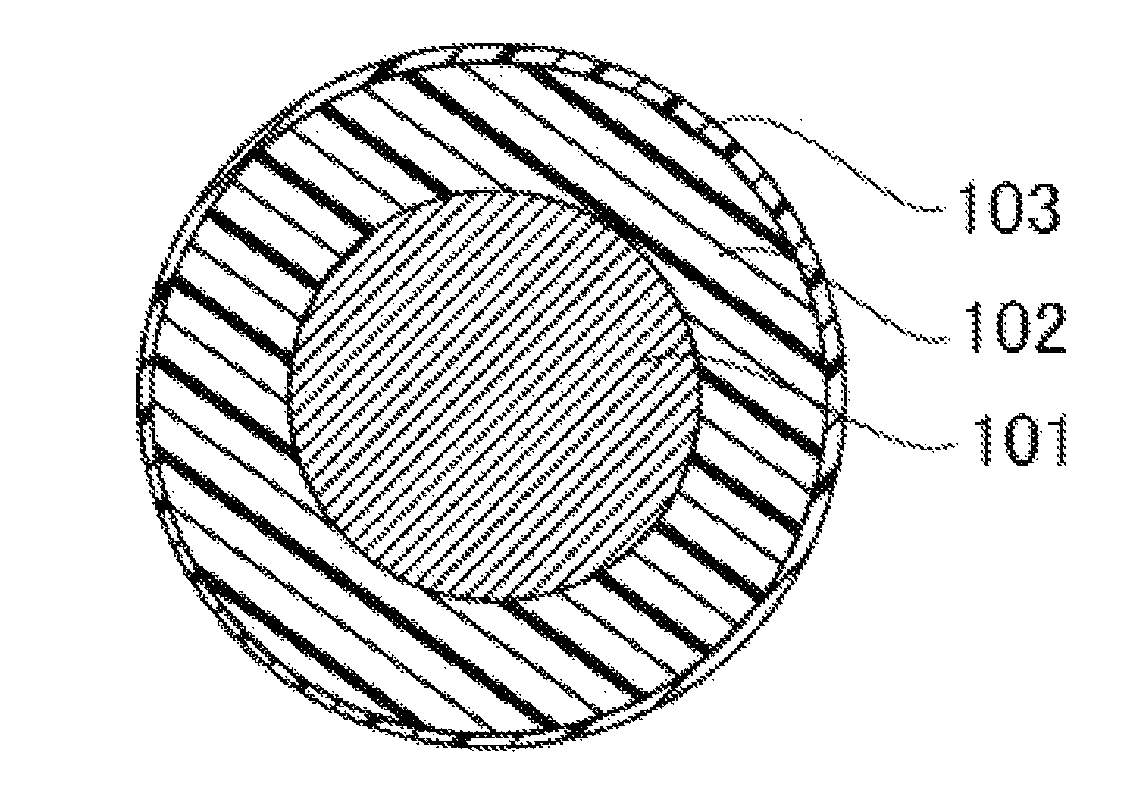
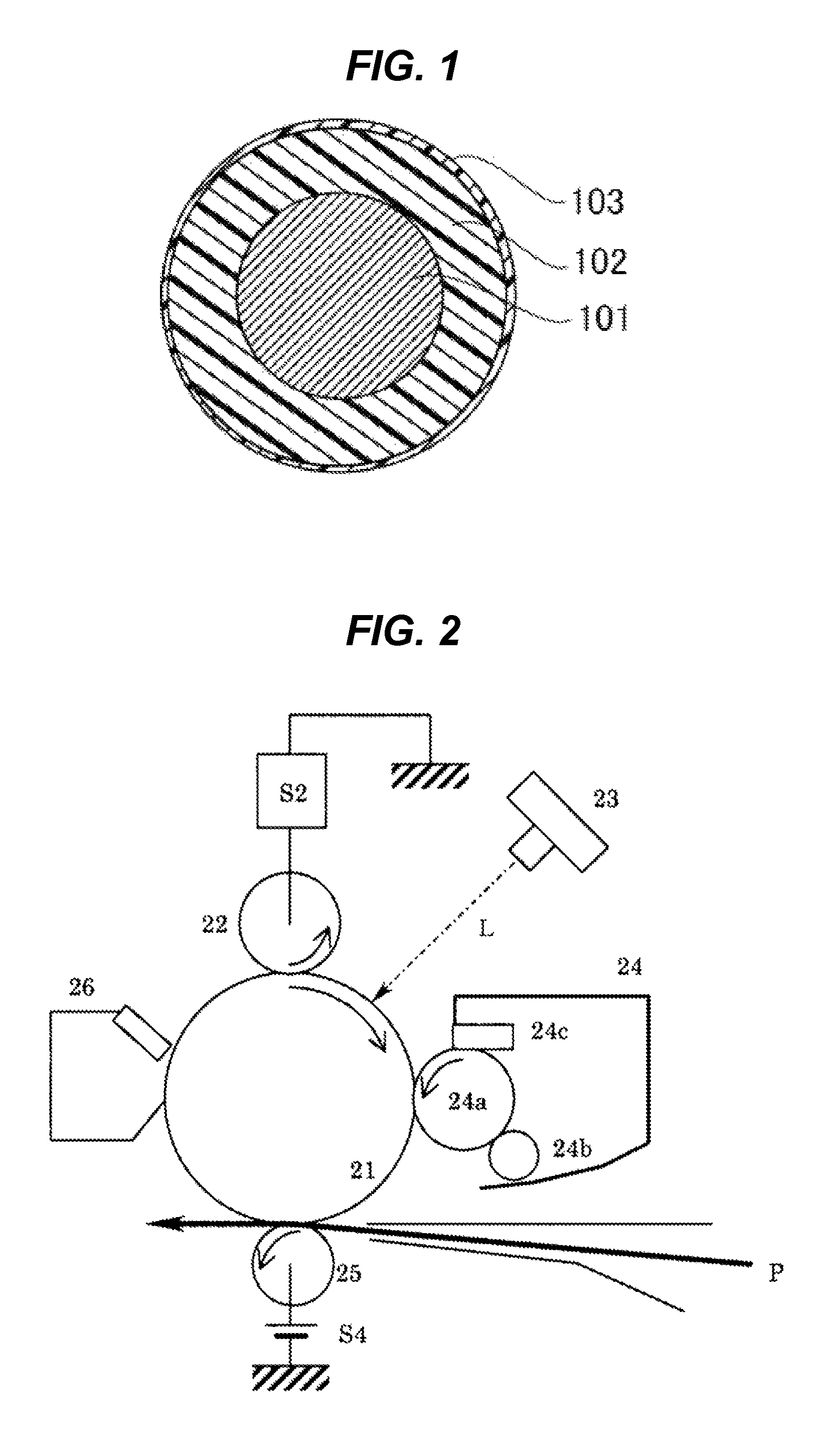
Provided are the following charging member and a method of producing the charging member. The charging member has an improved charging ability and hence alleviates, in particular, a positive ghost. The charging member can maintain resistance to the adhesion of toner, a toner external additive, or the like over a long time period. The charging member for an electrophotographic apparatus comprises an electro-conductive support, an electro-conductive elastic layer, and a surface layer, wherein the surface layer comprises a polymer compound having an Si—O—Ti linkage in a molecular structure thereof, and the polymer compound has each of constitutional units represented by a formula (1), a formula (2), and a formula (3) defined in the description. The method is a method of producing the charging member.

Description

CROSS-REFERENCE TO RELATED APPLICATIONS[0001]This application is a continuation of International Application No. PCT / JP2012 / 002627, filed Apr. 16, 2012, which claims the benefit of Japanese Patent Application No. 2011-099828, filed Apr. 27, 2011.BACKGROUND OF THE INVENTION[0002]1. Field of the Invention[0003]The present invention relates to a charging member to be used in an electrophotographic apparatus and a method of producing the charging member, a process cartridge, and an electrophotographic image-forming apparatus.[0004]2. Description of the Related Art[0005]A charging member that abuts on an electrophotographic photosensitive member to charge the electrophotographic photosensitive member is generally formed so as to have a rubber-containing elastic layer in order that an abutment nip between the electrophotographic photosensitive member and the charging member may be sufficiently and uniformly secured.[0006]In recent years, an additional improvement in durability has started...

Claims


Application Information

Patent Timeline
Patent Type & Authority Patents(United States)
IPC IPC(8): G03G15/02
CPCC08G77/14G03G15/02C09D183/14C08G77/58G03G15/0233Y10T428/31663C08G79/00
Inventor SUZUMURA, NORIKOKURODA, NORIAKIKODAMA, MASATAKATOMOMIZU, YUYAMASU, HIROKI
Owner CANON KK
Learn More