
Signal transmission method from a local network node

a signal transmission and local network technology, applied in the field of signals transmission methods, can solve the problems of long delay in transmission, inability to guarantee that data being retransmitted will be received without errors, and delays approaching 100 ms, so as to minimise the power needed and optimise the interference effect at the receiver

Active Publication Date: 2013-08-06
BISON PATENT LICENSING LLC
View PDF181 Cites 36 Cited by
  • Summary
  • Abstract
  • Description
  • Claims
  • Application Information

AI Technical Summary

Benefits of technology

This approach reduces transmission power, enhances reliability, and minimizes interference with macro-cell coverage by optimizing signal reception and transmission in pico-cells, improving overall communication efficiency.

Problems solved by technology

Although the acknowledged mode allows data to be received more reliably, when operating using the acknowledged mode of operation, the transmission may suffer long delays due to the transmission time across the link from the RNC to the UE via the Node B, and acknowledgements being sent back from the UE to the RNC.
Typically delays approaching 100 ms may occur.
In addition, there is no guarantee that the data being retransmitted will be received without errors, and consequently further re-transmissions may be required.
These delays, as well as un-reliable transmission will result in high delays and a reduced efficiency in the throughput for the link, which is undesirable.
In this arrangement, the downlink transmissions from the pico-cell will interfere with the downlink transmissions from the macro-cell, and the interference is likely to result in degradation in the coverage of the macro-cell.

Method used


Image

  • Signal transmission method from a local network node
  • Signal transmission method from a local network node
  • Signal transmission method from a local network node

Examples


Embodiment Construction

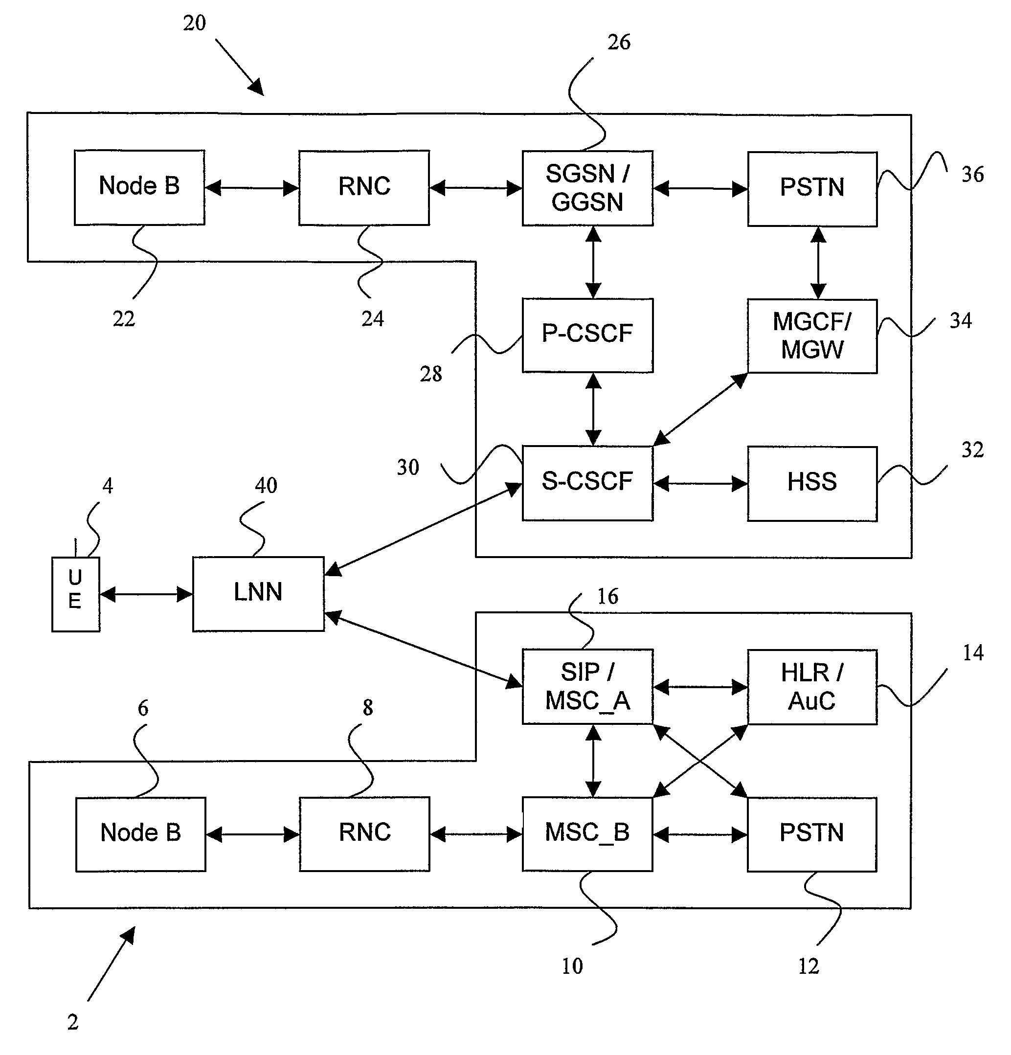
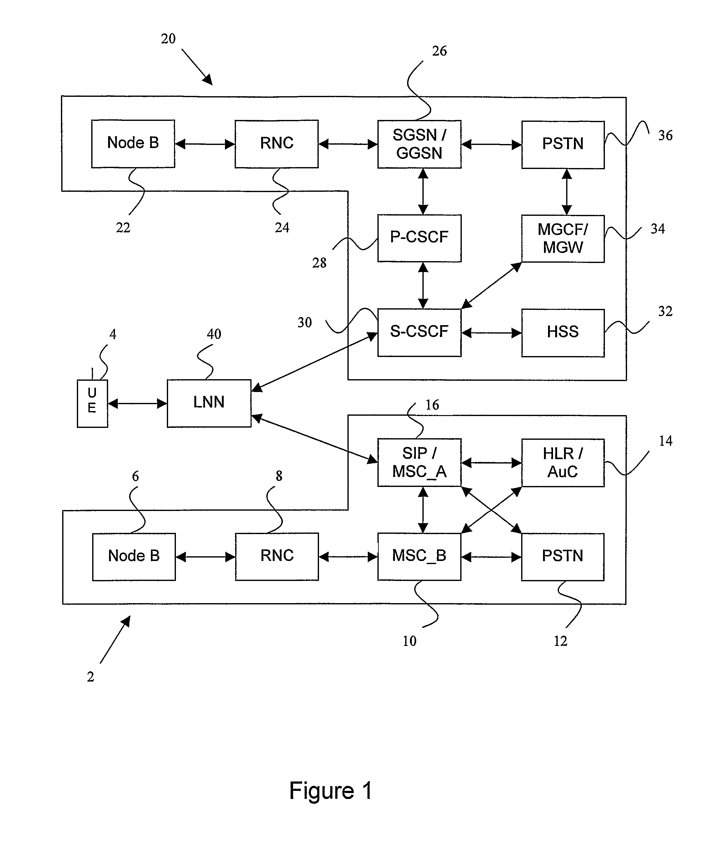
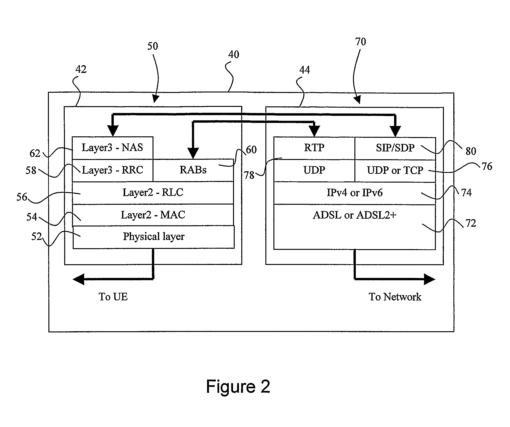
[0035]The operation of the Local Network Node embodying the invention will now be described in more detail with respect to FIGS. 2 and 3.

[0036]The LNN according to the preferred embodiment of the invention is both a transmitter and a receiver establishing a transmission link with a UE in the coverage cell provided by the LNN. The LNN is also arranged to convert 3G protocol messages received from the UE To SIP messages used to establish and maintain sessions on an Internet Protocol based network. The physical and logical structure of the LNN is illustrated in more detail in FIG. 2 to which reference should now be made.

[0037]The LNN comprises a User terminal side 42 comprising a standard 3G protocol processing stack for communicating with the User Terminal 4 over the air interface, and a Network Side 44 comprising Internet Protocol processing stack 70.

[0038]In known fashion, the 3G protocol stack contains Physical layer 52, above which are located the Layer 2 Medium Access Control (MA...


PUM


Abstract

A transmitter is provided having transmission methods that minimize the power needed to ensure reliable reception in a coverage area. In one aspect, data that requires re-transmission as acknowledged mode data is re-transmitted when the power level of the transmission link is higher than a pre-determined level set for reliable reception. The data rate of the re-transmitted data is set according to the difference in the actual power and the pre-determined level. In a second aspect, two transmitting antennae are used to transmit the same signals with a frequency off-set. The frequency off-set can be used to determine the phase of the signals being received at the receiver, so that a phase off-set can be introduced to optimise the effect of interference at the receiver.

Description

[0001]This application is a U.S. national phase application filed under 35 U.S.C. §371 of International application PCT / GB2005 / 003028, filed on Aug. 1, 2005, designating the United States, which claims the benefit of Great Britain Applications Nos. 0417020.5 and 0417021.3, filed on Jul. 30, 2004, which are hereby incorporated by reference herein.[0002]The invention relates to methods of transmission of signals between a transmitter and a mobile station, and in particular to methods for transmitting signals between a local network node and a user terminal such that the user terminal can connect to a 3G network.[0003]3G cellular communication systems and in particular the Frequency Division Duplex or Time Division Duplex (FDD / TDD) mode of the Wideband Code Division Multiple Access (WCDMA) system, defined by the Third Generation Partnership Project (3GPP), are known and are described in more detail at www.3gpp.org.[0004]The 3G cellular communication system provides subscribers with the...

Claims


Application Information

Patent Timeline
Patent Type & Authority Patents(United States)
IPC IPC(8): G08C17/00H04B7/005H04L1/18
CPCH04L1/1887H04L2027/0067
Inventor RICHARDSON
Owner BISON PATENT LICENSING LLC
Learn More