Melting furnace having a gas supplying apparatus

a technology of gas supply and melting furnace, which is applied in the direction of lighting and heating apparatus, furnaces, charge manipulation, etc., can solve the problems of difficult production of glass, ineffective flow of molten glass, and significant temperature difference in the molten material, so as to improve durability, improve the effect of installment structure and easy repair and maintenan

Active Publication Date: 2013-07-30
KOREA HYDRO & NUCLEAR POWER CO LTD
View PDF7 Cites 1 Cited by
  • Summary
  • Abstract
  • Description
  • Claims
  • Application Information

AI Technical Summary

Benefits of technology

[0016]Accordingly, the present invention has been made in view of the above problems, and the present invention is to provide a low temperature melting furnace including a gas supplying apparatus, which has a simple installment structure such that the gas supplying apparatus has improved durability under a high temperature environment and easy repair and maintenance is realized.

Problems solved by technology

Meanwhile, in the low temperature melting furnace, when internal molten material does not include a bubble due to an influence of water cooling of a wall and a bottom surface of the melting furnace, a significant temperature difference exists inside the molten material.
In this case, viscosity of the melting glass also has a wide distribution, and accordingly, a flow of the molten glass may not be effective due to a difference in viscosity such that the waste injected for vitrification may not be transmitted to an entire area of the molten glass.
In such circumstance, uniform molten glass is difficult to produce and a waste processing rate may be reduced.
Particularly, in the inductive heating low temperature melting furnace (or cold crucible induction melter), an operative problem may occur such that an arc in the metal sector may be generated due to a metal material formed in a lower portion of the chamber.
However, in the conventional oxygen supplying apparatus, an oxygen supplying pipe, and the cooling water inlet pipe and the cooling water outlet pipe for circulating the cooling water are fixed and supported by a separate casing and requires a cooling water pipe for cooling the oxygen supplying pipe separately from a cooling water circulation system for cooling the wall of the chamber 10, thereby adding complexity to the structure as well as causing difficulty in repair when breakdown occurs and inconvenience in maintenance.

Method used


Image

  • Melting furnace having a gas supplying apparatus
  • Melting furnace having a gas supplying apparatus
  • Melting furnace having a gas supplying apparatus

Examples


Embodiment Construction

[0026]Exemplary embodiments of the present invention will be described herein below with reference to the accompanying drawings.

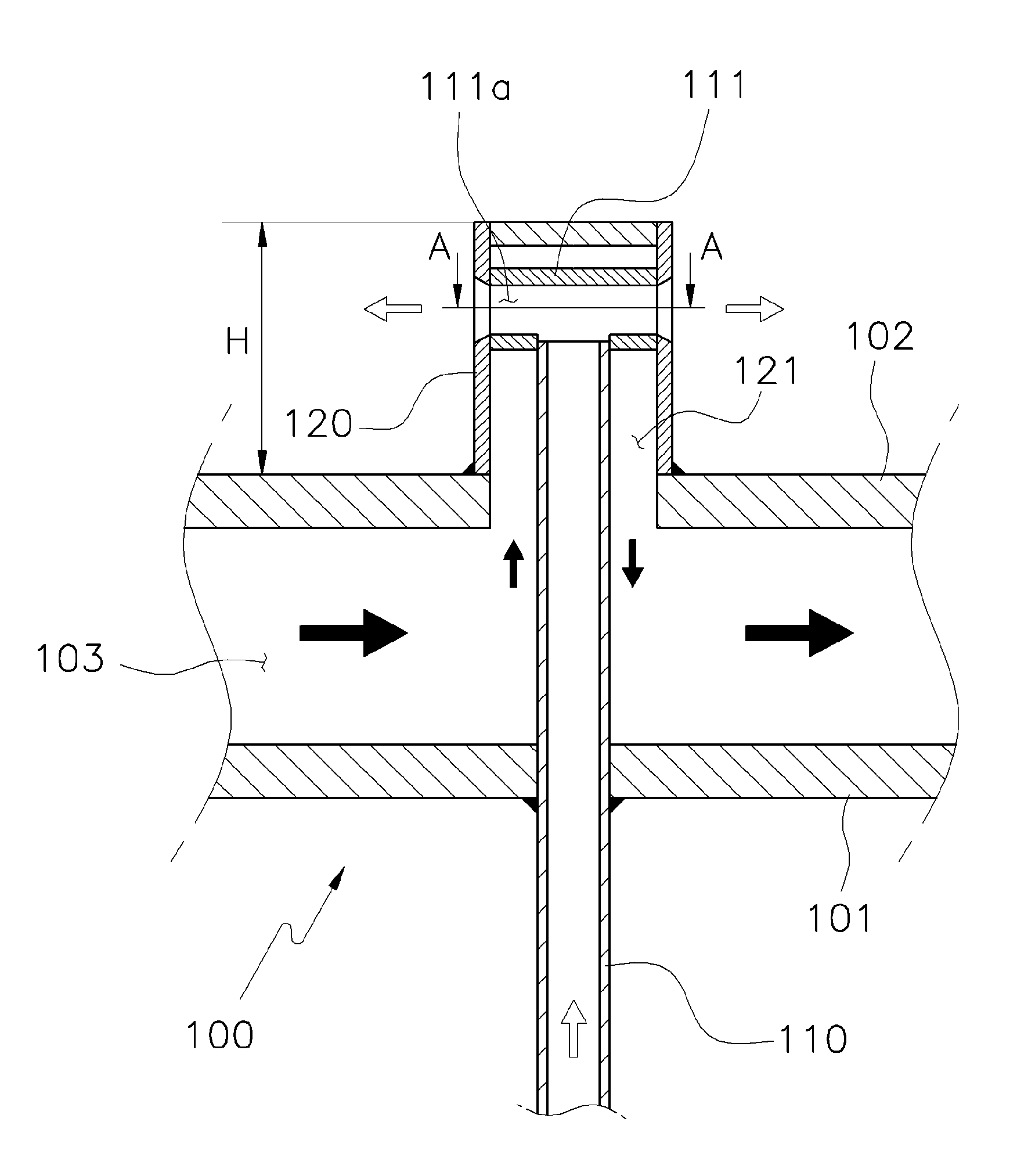
[0027]A low temperature melting furnace according to the present invention having a gas supplying unit that is formed to protrude inwardly of the melting furnace 100 to supply gas to the melting furnace 100 includes a gas supplying pipe 110 penetrating the melting furnace 100 and protruding inwardly of the melting furnace 100, a nozzle hole 111a being formed at a front end of the gas supplying pipe 110, and a cooling passage pipe 120 provided outside the gas supplying pipe 110 to include a second cooling passage 121 through which cooling liquid flows, the second cooling passage 121 being directly connected to a first cooling passage 103 through which the cooling liquid is circulated along a wall of the melting furnace 100.

[0028]The low temperature melting furnace 100 according to the present invention is configured in a double wall structure 101, 102 having...


PUM

PropertyMeasurementUnit
heightaaaaaaaaaa
diameteraaaaaaaaaa
frequencyaaaaaaaaaa

Abstract

A melting furnace includes a gas supplying unit configured to protrude inwardly of the melting furnace to supply a gas to the melting furnace, the gas supplying unit including a gas supplying pipe configured to penetrate the melting furnace to protrude inwardly of the melting furnace and configured to have a nozzle hole formed at a front end thereof; and a cooling passage pipe provided outside the gas supplying pipe to include a second cooling passage through which a cooling liquid flows, the second cooling passage being directly connected to a first cooling passage through which the cooling liquid is circulated along a wall of the melting furnace.

Description

CROSS REFERENCE[0001]This application claims the benefit under 35 U.S.C. §119 a of a Korean patent application filed in the Korean Intellectual Property Office on Sep. 19, 2011 and assigned Serial No. 10-2011-0094293, and the entire disclosure of which is hereby incorporated by reference.BACKGROUND OF THE INVENTION[0002]1. Field of the Invention[0003]The present invention relates to a melting furnace having a gas supplying apparatus, and more particularly, to a melting furnace having a gas supplying apparatus in which gas, particularly, for example, oxygen is provided to control a redox state of a vitrified molten material and stir the molten material to increase a processing capacity.[0004]2. Description of the Related Art[0005]It is highly important to safely dispose, store, and manage waste, particularly hazardous waste such as radioactive waste. One method for disposal and storage of the waste is vitrification, which disposes the waste by using glass. In this method, the waste s...

Claims


Application Information

Patent Timeline
Patent Type & Authority Patents(United States)
IPC IPC(8): H05B6/34H05B6/22C03B5/16
CPCC03B5/005C03B5/021C03B5/167F27D9/00C03B5/44F27D3/16F27D7/02C03B5/193G21F9/28G21F9/32
Inventor KIM, DEUK MANCHO, HYUN JECHOI, SEOK MOKIM, CHEON WOOHWANG, TAE WON
Owner KOREA HYDRO & NUCLEAR POWER CO LTD
Why Eureka
Try Eureka