Display device comprising an oxide semiconductor layer
a semiconductor layer and display device technology, applied in the field of semiconductor devices, can solve the problems of long time taken to reach the desired voltage, and obvious problems, and achieve the effect of long time taken to write a signal
- Summary
- Abstract
- Description
- Claims
- Application Information
AI Technical Summary
Benefits of technology
Problems solved by technology
Method used
Image
Examples
embodiment 1
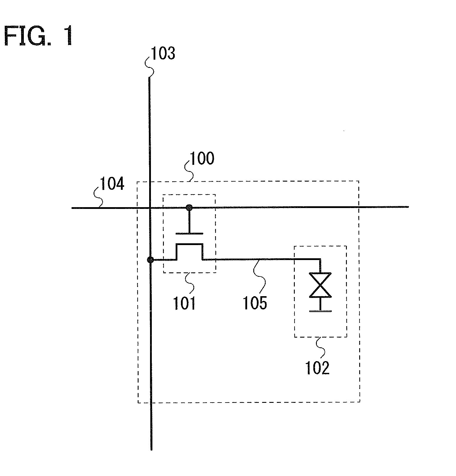
[0035]An example of a pixel in a liquid crystal display device is described with reference to FIG. 1. Elements included in a pixel 100 are a transistor 101 which functions as a switch element and a liquid crystal element 102.
[0036]A gate of the transistor 101 is electrically connected to a wiring 103 (a gate signal line). One of a source and a drain of the transistor 101 is electrically connected to a wiring 104 (a source signal line). The other is electrically connected to the liquid crystal element 102.
[0037]In this embodiment, an intrinsic or substantially intrinsic oxide semiconductor is used as the semiconductor material of the transistor 101, and the off-state current per micrometer of the channel width of the transistor 101 is 1×10⁻¹⁷ A or less (1×10⁻¹⁷ A / μm or less).
[0038]When the off-state current of the transistor 101 is 1×10⁻¹⁷ A / μm or less, it means that the amount of leakage current is substantially zero when the transistor 101 is off. In other words, the potential of a...
embodiment 2
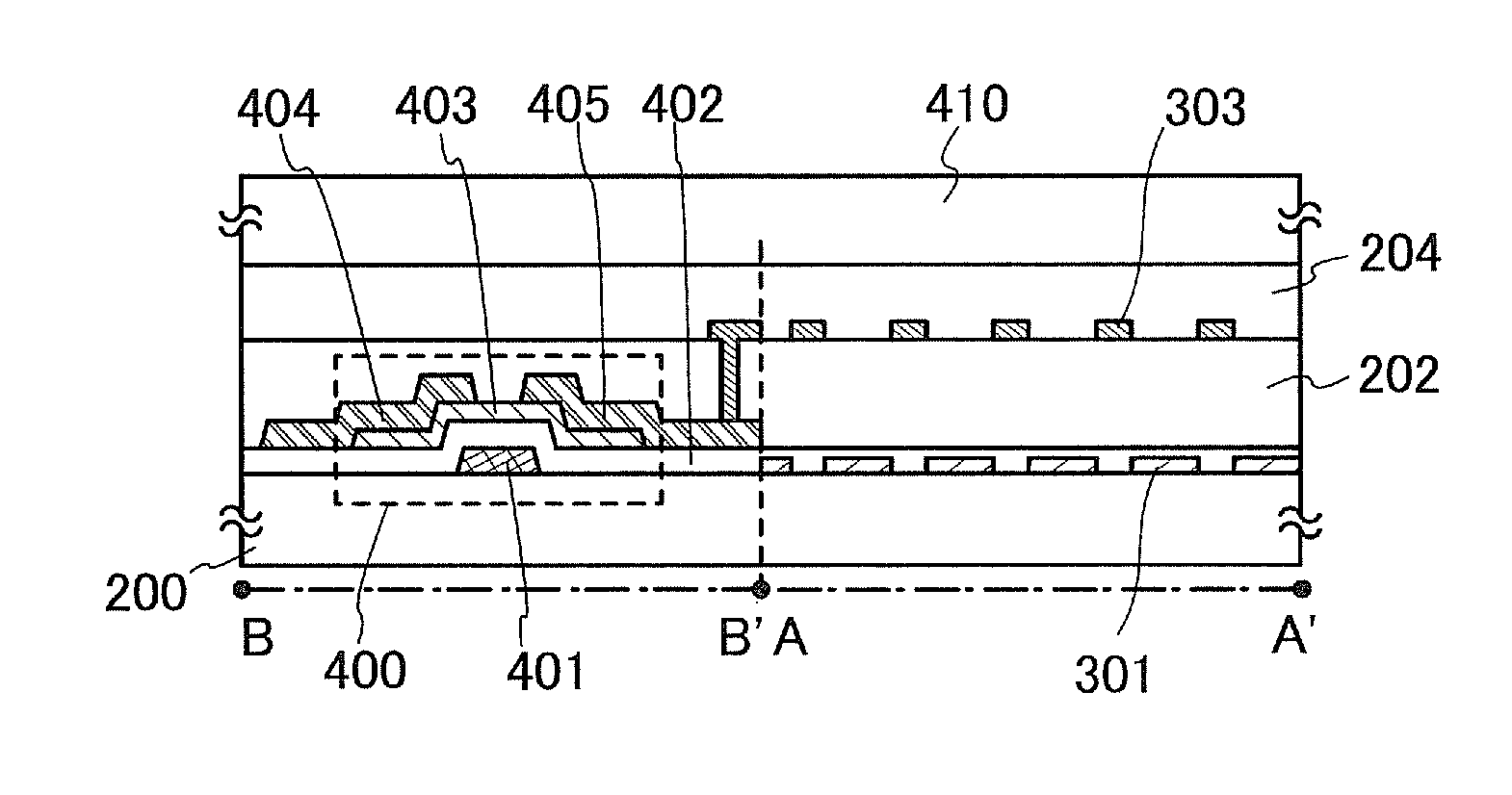
[0072]In this embodiment, the case where an FFS mode is used as the display method of a liquid crystal display device is described.
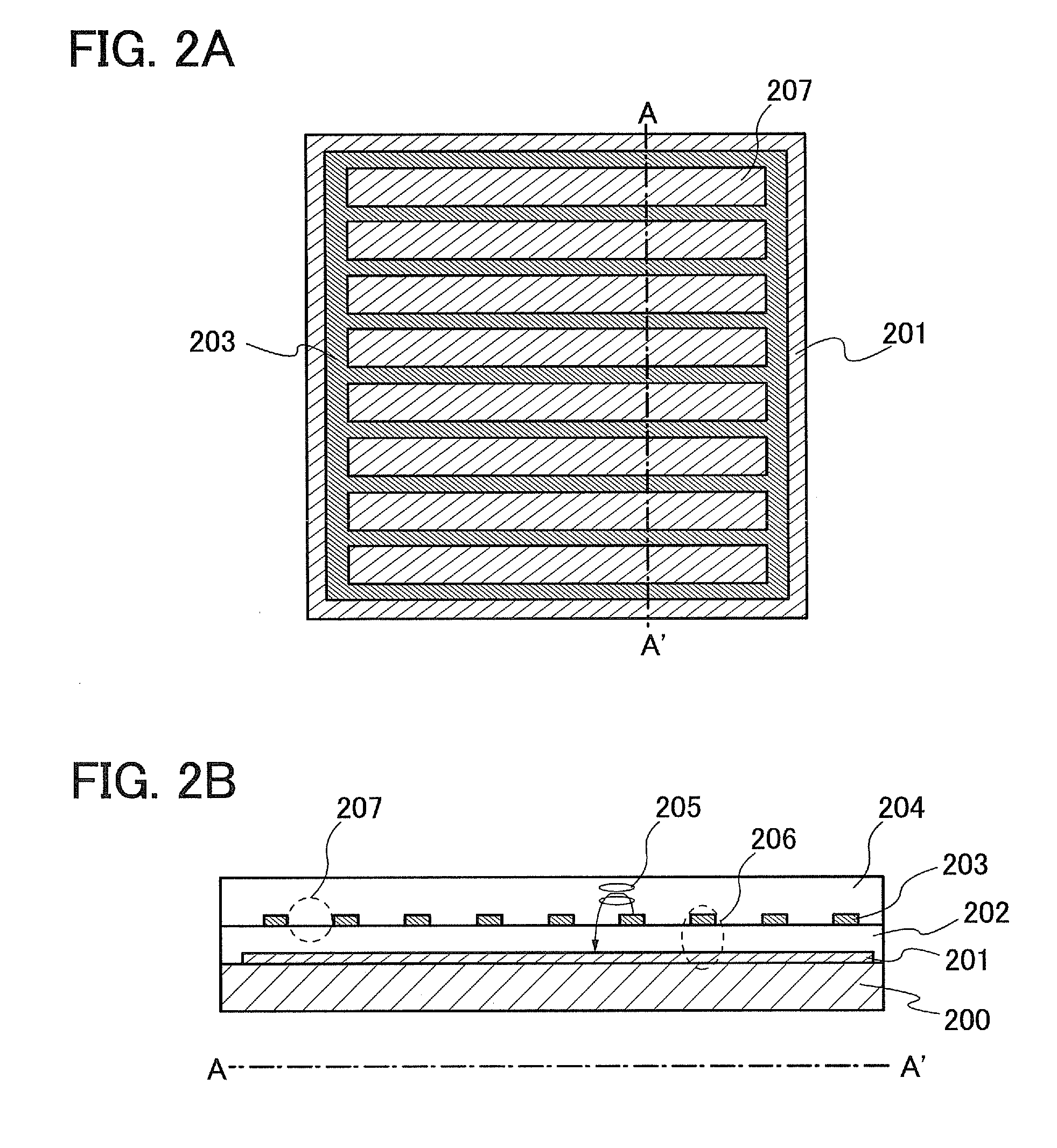
[0073]First, FIGS. 2A and 2B illustrate an example of an electrode structure in a pixel with a conventional FFS mode. In FIGS. 2A and 2B, the liquid crystal element 5002 in the pixel circuit in FIG. 13 is illustrated. FIG. 2A is a top view and FIG. 2B is a cross-sectional view.
[0074]In FIGS. 2A and 2B, an electrode 201 is formed over a substrate 200; an insulating film 202 is formed so as to cover the electrode 201; an electrode 203 is formed over the insulating film 202; and a liquid crystal layer 204 is formed over the electrode 203. One of the electrode 201 and the electrode 203 is a pixel electrode. The other is a common electrode. The electrode 203 has a slit 207 (an opening portion). The electrode 201 is a plate-like (a shape covering the entire surface) electrode. The insulating film 202 may be a single layer or a stacked layer.
[0075]When a horizo...
embodiment 3
[0093]In this embodiment, an example of a method for manufacturing a semiconductor device is described with reference to FIGS. 9A to 9E.
[0094]First, after a conductive film is formed over a substrate 1000 having an insulating surface, a gate electrode 1001 is formed in a first photolithography process. End portions of the gate electrode 1001 are preferably tapered because coverage with a gate insulating film stacked thereover is improved.
[0095]Although there is no particular limitation on a substrate which can be used as the substrate 1000 having an insulating surface, it is necessary that the substrate have at least heat resistance high enough to withstand heat treatment to be performed later. For example, various kinds of glass substrates can be used.
[0096]In the case where the temperature of the heat treatment to be performed later is high, a substrate whose strain point is higher than or equal to 730° C. is preferably used as a glass substrate. For the glass substrate, for examp...
PUM
 Abstract
Description
Claims
Application Information
 - R&D
- Intellectual Property
- Life Sciences
- Materials
- Tech Scout
- Unparalleled Data Quality
- Higher Quality Content
- 60% Fewer Hallucinations
Browse by: Latest US Patents, China's latest patents, Technical Efficacy Thesaurus, Application Domain, Technology Topic, Popular Technical Reports.
© 2025 PatSnap. All rights reserved.Legal|Privacy policy|Modern Slavery Act Transparency Statement|Sitemap|About US| Contact US: help@patsnap.com


