
Vapor deposition reactor for forming thin film

a technology of vapor deposition reactor and vapor deposition reactor, which is applied in the direction of chemical vapor deposition coating, coating, metallic material coating process, etc., can solve the problems of changing the properties of semiconductor devices and expensive valves that sequentially, and achieves the effect of simplifying the vapor deposition process, reducing the area or volume and increasing the area efficiency of the vapor deposition reactor

Inactive Publication Date: 2013-06-25
VEECO ALD
View PDF98 Cites 209 Cited by
  • Summary
  • Abstract
  • Description
  • Claims
  • Application Information

AI Technical Summary

Benefits of technology

This design enhances area efficiency, reduces the complexity of the deposition process, and improves the reliability of thin film formation by minimizing substrate exposure to chamber atmosphere, leading to precise control over interface reactions and increased productivity.

Problems solved by technology

In some cases, even a slight reaction may change properties of semiconductor devices.
However, if the design rule is about 32 nm or smaller, as in nano devices or quantum devices, the reactions at the interface or the unwanted formation of interface may become relevant.
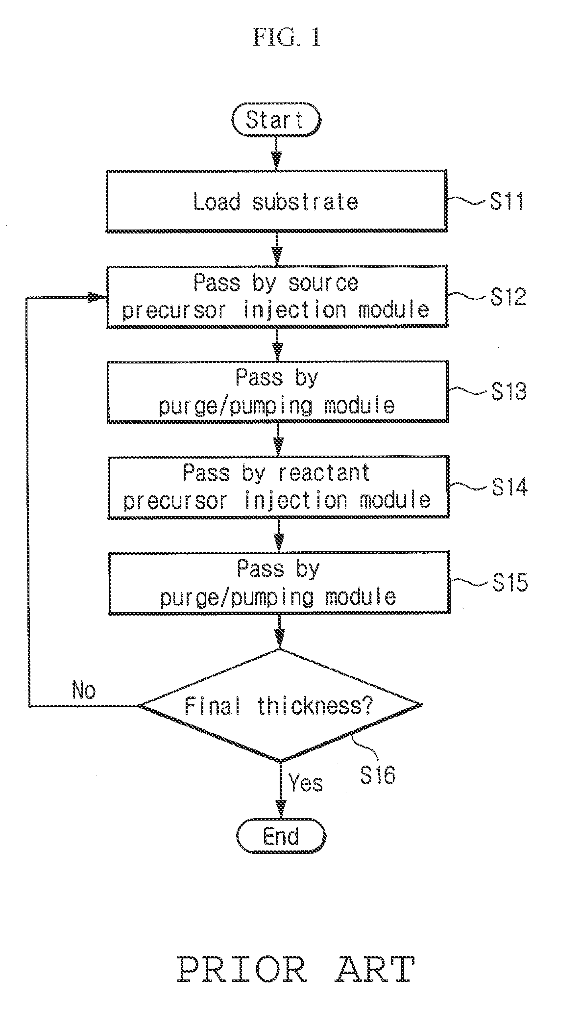
To perform these steps, an expensive valve that sequentially supplies the source precursor, purge gas, reactant precursor, and a purge gas to the substrate is needed.

Method used


Image

  • Vapor deposition reactor for forming thin film
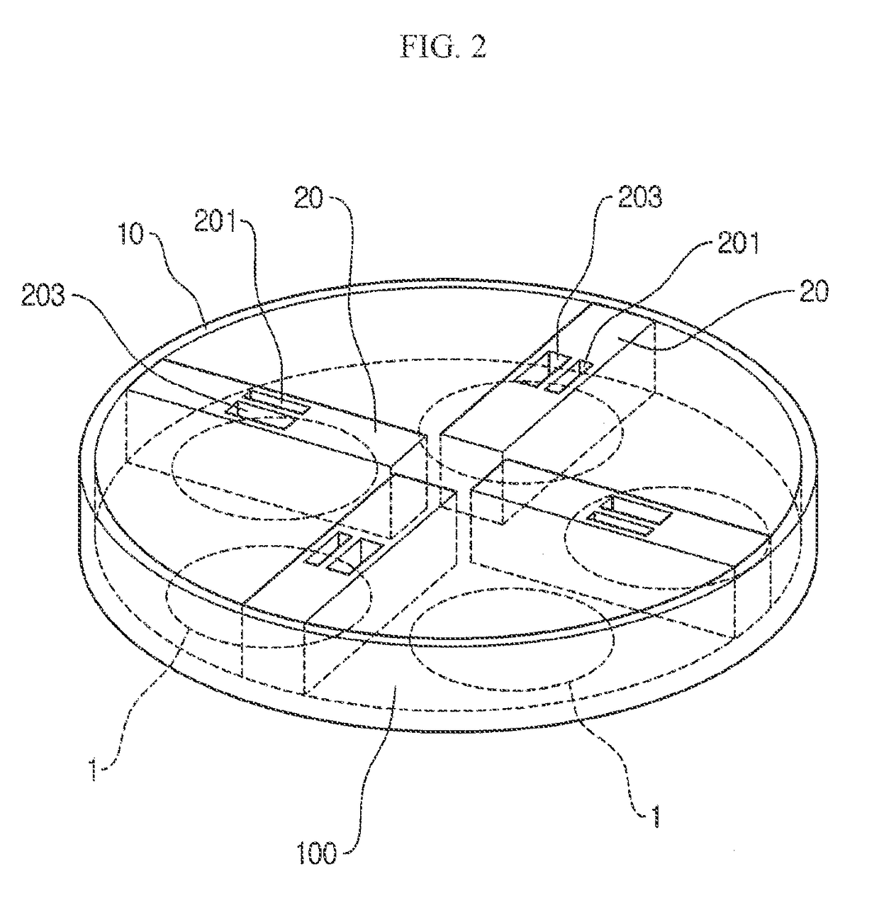
  • Vapor deposition reactor for forming thin film
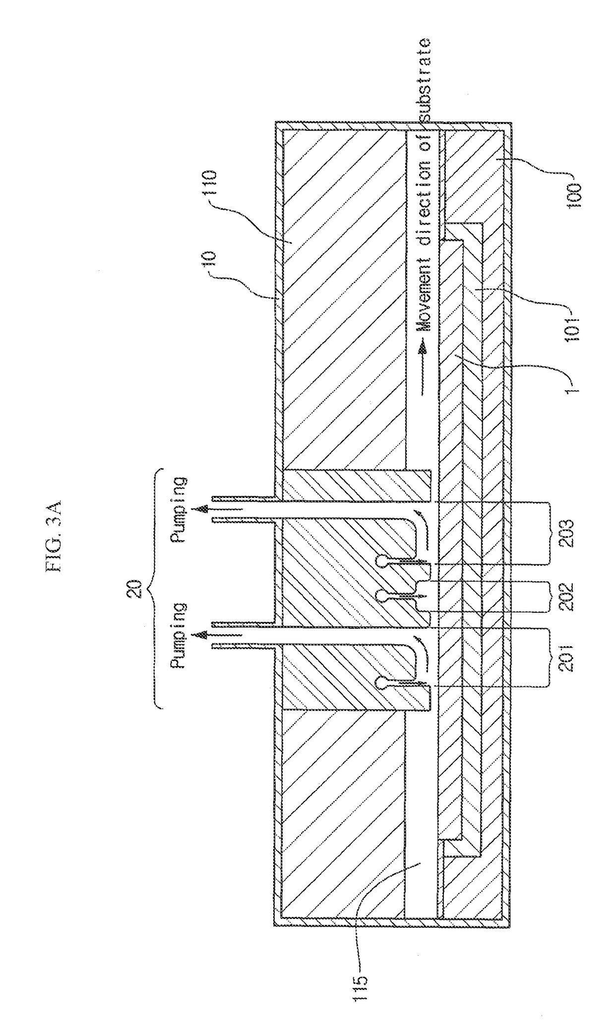
  • Vapor deposition reactor for forming thin film

Examples


Embodiment Construction

[0034]Embodiments are described herein with reference to the accompanying drawings. Principles disclosed herein may, however, be embodied in many different forms and should not be construed as being limited to the embodiments set forth herein. In the description, details of well-known features and techniques may be omitted to avoid unnecessarily obscuring the features of the embodiments.

[0035]The terminology used herein is for the purpose of describing particular embodiments only and is not intended to be limiting of this disclosure. As used herein, the singular forms “a”, “an” and “the” are intended to include the plural forms as well, unless the context clearly indicates otherwise. Furthermore, the use of the terms a, an, etc. does not denote a limitation of quantity, but rather denotes the presence of at least one of the referenced item. The use of the terms “first”, “second”, and the like does not imply any particular order, but they are included to identify individual elements....


PUM

PropertyMeasurementUnit
adsorptionaaaaaaaaaa
pressureaaaaaaaaaa
flow rateaaaaaaaaaa

Abstract

A vapor deposition reactor includes a chamber filled with a first material, and at least one reaction module in the chamber. The reaction module may be configured to make a substrate pass the reaction module through a relative motion between the substrate and the reaction module. The reaction module may include an injection unit for injecting a second material to the substrate. A method for forming thin film includes positioning a substrate in a chamber, filling a first material in the chamber, moving the substrate relative to a reaction module in the chamber, and injecting a second material to the substrate while the substrate passes the reaction module.

Description

CROSS-REFERENCE TO RELATED APPLICATION[0001]This application claims priority under 35 U.S.C. §119(e) to U.S. Provisional Patent Application No. 61 / 088,674, filed on Aug. 13, 2008, which is incorporated by reference herein in its entirety.BACKGROUND[0002]1. Field of Art[0003]This invention relates to a vapor deposition reactor and a method for forming thin film on a substrate.[0004]2. Description of the Related Art[0005]Semiconductor materials include silicon-based semiconductors such as Si and SiGe, metal oxide semiconductors such as ZnO, group III-V compound semiconductors such as GaAs, GaP, GaN, AlGaAs and InP; and group II-VI compound semiconductors such as CdSe, CdTe, ZnS and CdHgTe. Semiconductor devices are manufactured using these as substrate material, forming metal films or insulating films on the substrate material, and carrying out processes such as photolithography, etching, cleaning and thin film deposition.[0006]When fabricating a metal-oxide-semiconductor field-effect...

Claims


Application Information

Patent Timeline
Patent Type & Authority Patents(United States)
IPC IPC(8): H01L21/31
CPCC23C16/45551H01L21/4814H01L21/02521
Inventor LEE, SANG IN
Owner VEECO ALD
Learn More