
Chemical vapor deposition reactor and method

a chemical vapor deposition and reactor technology, applied in the direction of chemically reactive gases, crystal growth process, polycrystalline material growth, etc., can solve the problems of increasing the consumption of reactant gases, reducing the efficiency of cvd processes, and non-uniform deposition, so as to reduce the complexity and cost of building, reduce the consumption of reactants, and uniform deposited layers

Inactive Publication Date: 2013-06-18
LI GANG
View PDF7 Cites 0 Cited by
  • Summary
  • Abstract
  • Description
  • Claims
  • Application Information

AI Technical Summary

Benefits of technology

The design achieves uniform deposition, reduced reactant consumption, and improved reproducibility and scalability of CVD processes, enabling larger wafer capacities with reduced operational complexity and costs.

Problems solved by technology

For an outwardly radial flow of reactant gases, the mass density of reactants in the gas phase decreases due to gradually increased cross-section, which forms another inherent source of non-uniform deposition in such a cylindrical chamber.
One contemporary approach to mitigate the depletion effect is to use a high gas flow rate to reduce the concentration gradient along the flow direction, but the drawback of this approach is an inherent decrease in efficiency of CVD processes and an increased consumption of reactant gases.
Making such kinds of the susceptor capable of rotating multiple wafers and / or satellites in a sealed chamber under very dynamic CVD conditions is inherently expensive and complicated, which has impeded a further increase of the wafer capacity of the planetary reactor.
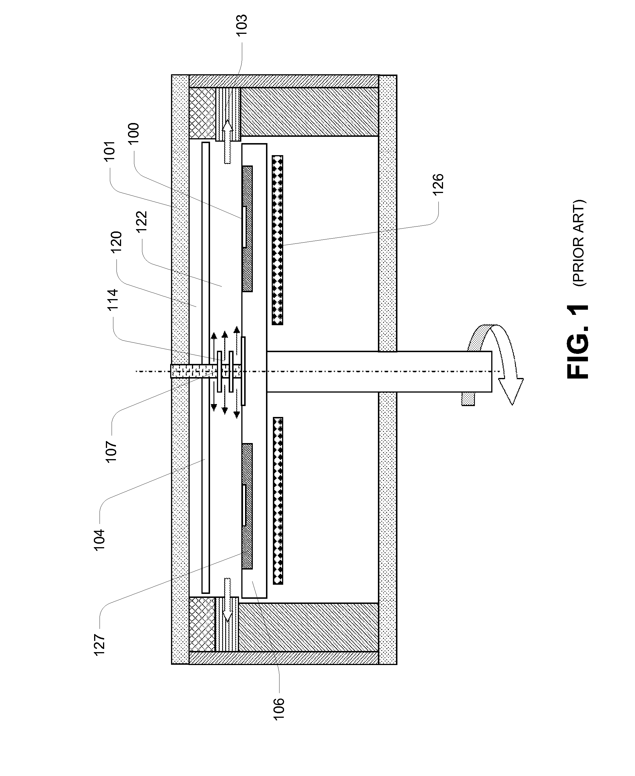
Furthermore, referring to FIG. 1, due to lack of active gases flowing through, heavy deposits are inherently accumulated on the down surface of the quartz plate 104, which not only depletes the reactants but also deteriorates CVD processing.
It is inherently difficult to maintain or clean the lid 101 in routine operation.
As a result, repeatability, reproducibility and consistency of the CVD processes can not be ensured.
Deformation of the lid 101 under low pressures also influences CVD processing and further impedes the scale up of the cylindrical chamber size in diameter.
Particularly at high pressures and temperatures, thermal convection occurs severely in a large volume of chamber.
The gas flow tends to be undesirably turbulent.
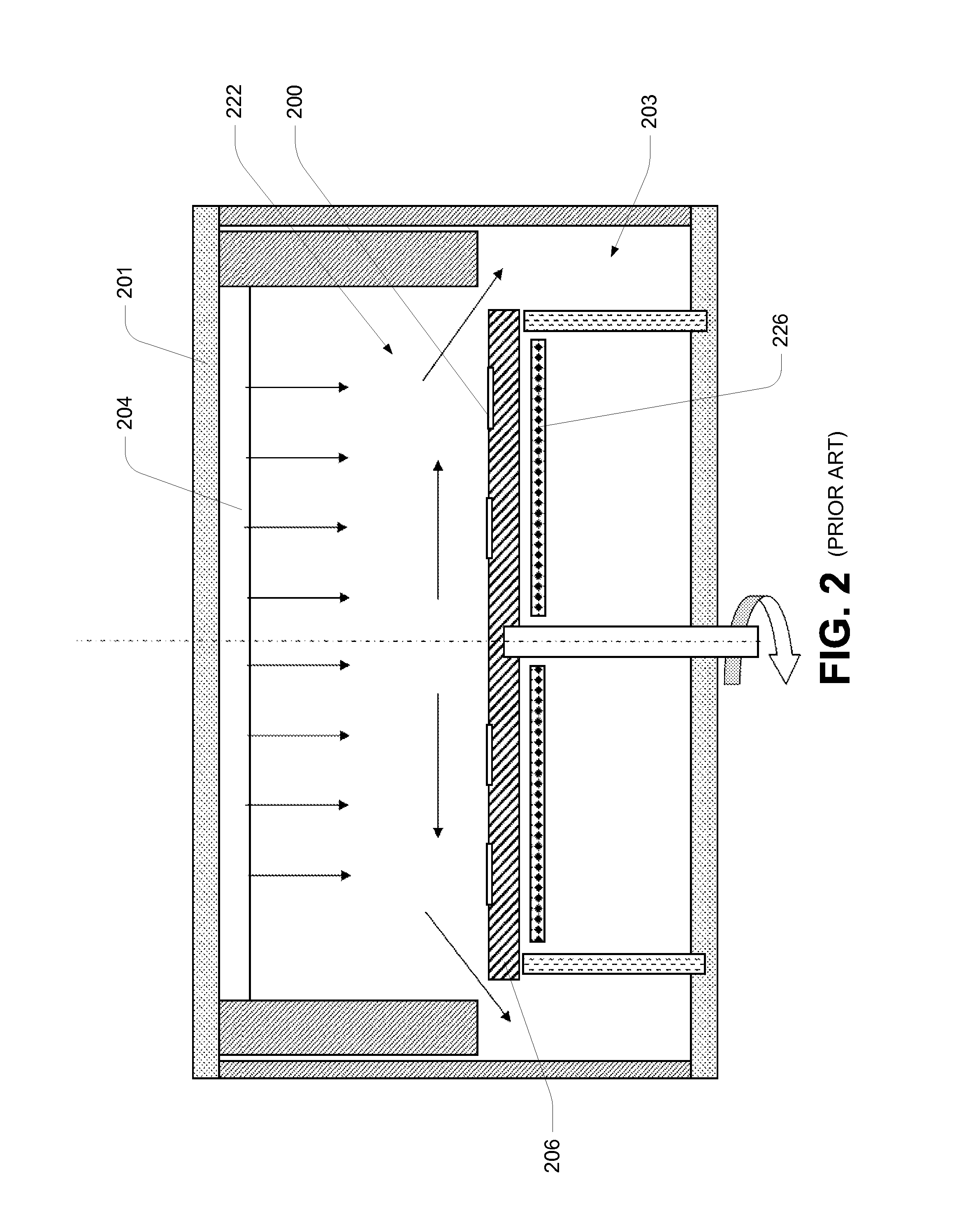
One of the drawbacks is an increased consumption of reactants, and the other is that to spin a large wafer carrier at a very high speed substantially without wobbling is inherently extremely difficult.
Deformation of the lid 201 under low pressures may influence CVD processing and further impedes the scale up of the cylindrical chamber size in diameter.
However, the showerhead 304 is inherently complicated and expensive.
Complex water passages around fine orifices face a great risk of leaks.
The presence of thousands of separate fine orifices prevents easy and reproducible cleaning after CVD processing.
As a result, repeatability, reproducibility and consistency of the CVD processes can not be ensured.
Deformation of the lid 301 under low pressures also influences CVD processing and further impedes the scale up of the cylindrical chamber size in diameter.
However, the horizontal gas stream still suffers undesired longitudinal depletion effect.
For this type of a non-cylindrical chamber, the side-wall effect on flowing pattern perpendicular to the horizontal gas flow direction can deteriorate uniformity of depositing layers and reduce efficiency of CVD processes, which inherently prevents to build up a large size chamber.
The thermal and mechanical stress may consequently tend to break top plates prematurely at great costs.
So, the aforementioned reactors suffer from inherent deficiencies that tend to detract from their overall utility and desirability.

Method used


Image

  • Chemical vapor deposition reactor and method
  • Chemical vapor deposition reactor and method
  • Chemical vapor deposition reactor and method

Examples


Embodiment Construction

[0047]The invention and its various embodiments can now be better understood by turning to the following detailed description of the preferred embodiments which are presented as illustrated examples of the invention defined in the claims. It is expressly understood that the invention as defined by the claims may be broader than the illustrated embodiments described below.

[0048]Many alterations and modifications may be made by those having ordinary skill in the art without departing from the spirit and scope of the invention. Therefore, it must be understood that the illustrated embodiment has been set forth only for the purposes of example and that it should not be taken as limiting the invention as defined by the following claims.

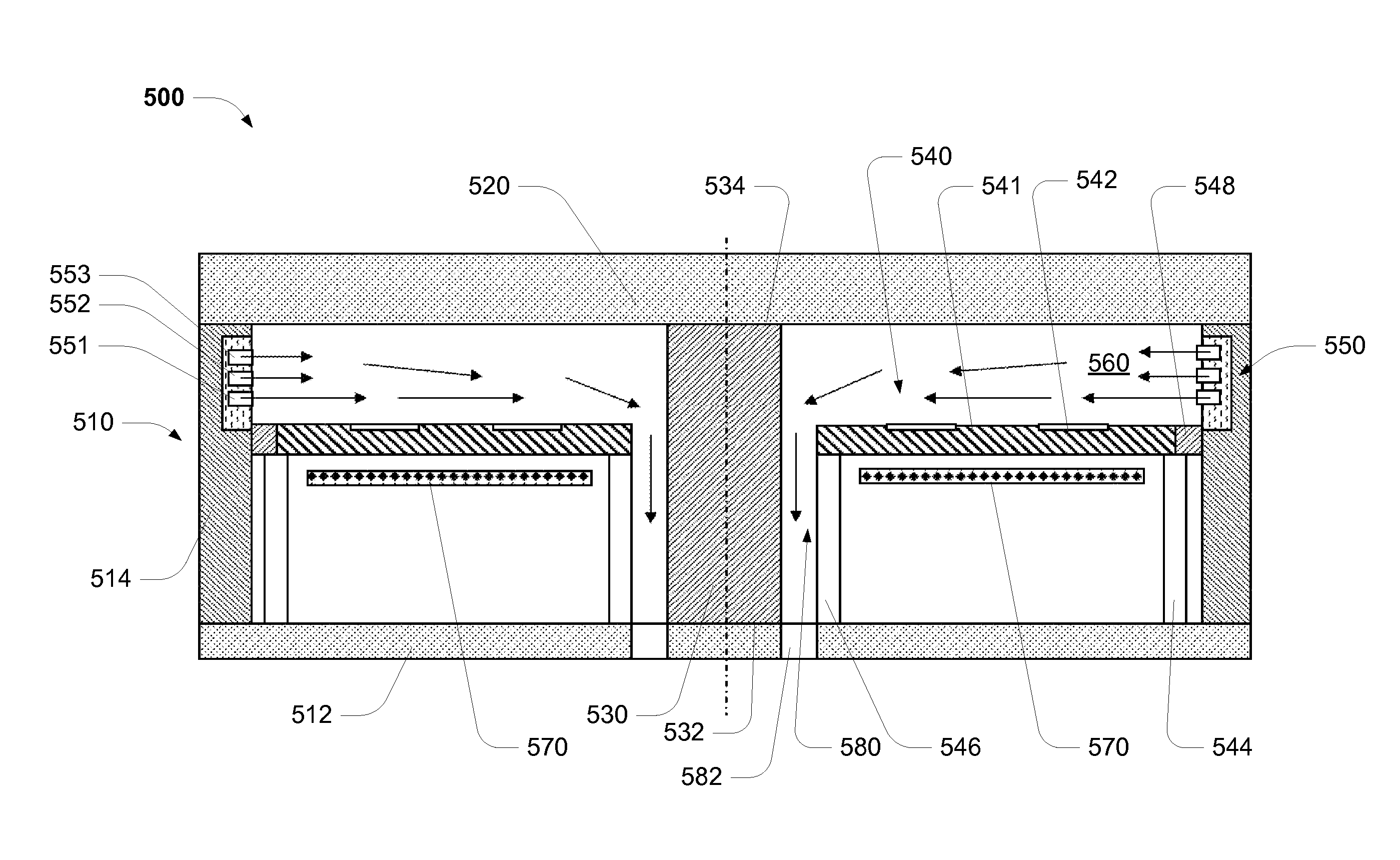
[0049]Referring to FIG. 5, it will be appreciated that an embodiment reactor apparatus 500 for chemical vapor deposition, comprises:[0050]a reactor body 510 defining a reaction chamber 560;[0051]a close element 520 for operatively (or substantially) sealin...


PUM

PropertyMeasurementUnit
outer perimeteraaaaaaaaaa
mass densityaaaaaaaaaa
concentrationaaaaaaaaaa

Abstract

A reactor and method for performing chemical vapor deposition are disclosed. A chemical vapor deposition reactor can have a cylindrical chamber that comprises a cylindrical lid support and an annular gas distribution plate. Said chamber can be configured to have a horizontal laminar flow of at least one gas stream in the radial direction and a vertical downward flow of another gas stream over wafers. A large capacity of a CVD reactor with simple structures, easy maintenance and low consumption of reactants can be achieved. High uniformity, repeatability, reproducibility and consistency of depositing layers on wafers can be obtained.

Description

TECHNICAL FIELD OF INVENTION[0001]The present invention relates generally to a reactor and method for performing chemical vapor deposition (CVD).[0002]The invention has been developed primarily for use as a CVD reactor having a cylindrical chamber for deposition of crystalline layers on one or more likewise crystalline substrates and will be described hereinafter with reference to this application. However, it will be appreciated that the invention is not limited to this particular field of use.BACKGROUND[0003]Any discussion of the prior art throughout the specification should in no way be considered as an admission that such prior art is widely known or forms part of the common general knowledge in the field.[0004]In general, the gas flow dynamics for high quality layers deposited by CVD favors laminar flow Laminar flow, as oppose to convective flow, is required to achieve high efficiency of CVD processes and high uniformity of deposited layers.[0005]Referring now to FIG. 1, one ty...

Claims


Application Information

Patent Timeline
Patent Type & Authority Patents(United States)
IPC IPC(8): C23C16/458
CPCC23C16/4412C23C16/45504C23C16/45508C23C16/45574C23C16/4558C30B25/14C30B29/403
Inventor LI, GANG
Owner LI GANG
Learn More