
Optically guided munition control system and method

a control system and technology of a guided munition, applied in the field of armaments, can solve the problems of low accuracy, unguided munitions are subject to aim error and wind disturbance, and mortars are becoming less effective in today's precision combat environment, and achieve low cost, low volume stability, and cost-effective

Active Publication Date: 2013-05-28
BAE SYST INFORMATION & ELECTRONICS SYST INTERGRATION INC
View PDF41 Cites 11 Cited by
  • Summary
  • Abstract
  • Description
  • Claims
  • Application Information

AI Technical Summary

Benefits of technology

The present invention provides a cost-effective guided munition that uses an optical seeker and a low volume stability augmentation system. The technique is compatible with other munitions and applications, and is simple and robust with low false alarm rate. The invention also includes an algorithm for interface with an infrared seeker design that results in significant improvement in detection and cost reduction. The guidance and control system is mounted on printed circuit boards that are compact and can withstand G forces during launch and ballistic flight toward the target. The control and guidance system includes three MEMS gyros to sense the body yaw, pitch, and roll, which provide signals to a flight control subsystem to deroll the munition and correct range and aiming errors based upon the detected signals from the optical seeker.

Problems solved by technology

One of the major disadvantages of mortars is their comparatively low accuracy, and as a result mortars are becoming less effective in today's precision combat environment.
Unguided munitions are subject to aim error and wind disturbances.
These often cause the munition to miss the target completely or require many rounds to complete the fire mission due to the large CEP (Circular Error Probability).
Current approaches to guided weapons are expensive and are used on larger long range weapons.
Mortars, if guided at all, are guided by an expensive guidance and control (G&C) system.
The cost is high for current guided mortars and unguided mortars have poor accuracy.
Also, unguided mortars result in unacceptable collateral damage, excess cost due to large number of rounds required to blanket target area, and expose the mortar crew to counterbattery fire due to large time required to drop the necessary shells to saturate the target.
Existing prior art guidance systems and methods use algorithms that may be computationally inefficient, require excessive input information, are incompatible with new sensor designs and require expensive support hardware (seeker implementation).
Furthermore, there is a need for a highly efficient detection / tracking algorithm compatible with optical hardware and limited processing capability associated with small caliber precision guided weapons design.

Method used


Image

  • Optically guided munition control system and method
  • Optically guided munition control system and method
  • Optically guided munition control system and method

Examples


Embodiment Construction

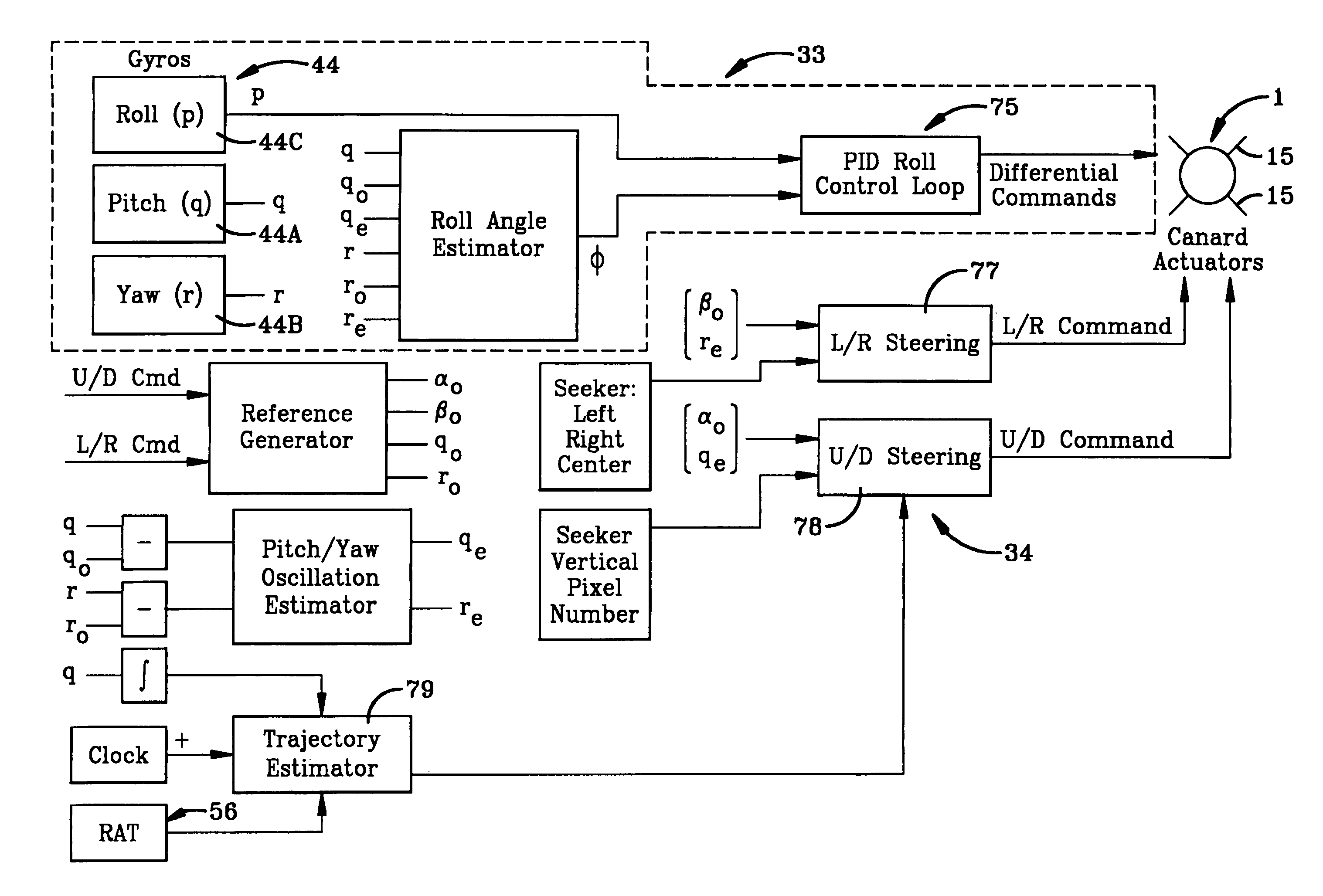
[0032]A preferred embodiment of the control system and method of the present invention for optically guiding a munition toward a target is shown diagrammatically in FIG. 1. The optically guided munition is indicated generally at 1, and preferably is a mortar, such as a 60 mm mortar. An example of such a mortar shell or round is shown in FIGS. 2 and 3. Mortar 1 includes a main body 3 formed with a hollow interior in which is contained an explosive charge. At the rear of body 3 will be usual aerodynamic stabilizing fin 5 with a propellant charge being located within an adjacent housing 7. In accordance with one of the features of the invention, a replacement fuse indicated generally at 10 is mounted on the front or fore portion of body 3, preferably by a threaded connection at 12. Fuse 10 includes a housing 11 having a tapered front portion 13 on which is mounted a plurality of guidance canards 15. Fuse 10 replaces a standard nose / fuse construction used with body 3, and thus enables t...


PUM


Abstract

An optically guided munition and control system has a replacement fuse assembly mounted on the front of a munition body or shell casing. An optical seeker subsystem detects an illuminated target and supplies signals to a processor. The processor develops steering commands sent to a flight control subsystem having a plurality of guidance canards which are actuated by drive motors through gear assemblies. The roll of the munition is established and left / right and up / down steering commands are sent to the canard drive motors based upon the optical seeker subsystem detection of the target illuminator. Range adjustment is based upon bore sight lockdown angle and cross range control is based upon left / right centering error. A code is contained in the optical radiation received from the illuminated target which must be validated by a preset code in the system processor to arm the munition.

Description

CROSS REFERENCE TO RELATED APPLICATION[0001]This application claims rights under 35 USC 119(e) from U.S. application Ser. No. 60 / 650,718, filed Feb. 7, 2005; the contents of which are incorporated herein by reference.BACKGROUND OF THE INVENTION[0002]1. Field of the Invention[0003]The present invention relates to armaments and more particularly to guided munitions. More particularly, the invention relates to a system and method for optically guiding a munition following a ballistic path toward a target by processing optical signals from an optical source located at the target and controlling the roll of the munition to generate flight control signals fed to a plurality of flight control canards mounted on the munition.[0004]2. Background Information[0005]Mortars are one of the most commonly employed weapons in a ground combat unit. The traditional role of mortars has been to provide close and continuous fire support for maneuvering forces. Military history has repeatedly demonstrated...

Claims


Application Information

Patent Timeline
Patent Type & Authority Patents(United States)
IPC IPC(8): F42B15/01F42B10/62F42B10/00F42B15/00
CPCF41G7/222F41G7/226F41G7/2293F42B15/01G05D1/12
Inventor MAYNARD, JOHN A.CARLSON, MARK A.ZEMANY, PAUL D.
Owner BAE SYST INFORMATION & ELECTRONICS SYST INTERGRATION INC
Learn More